Verilink 400 (CG) Configuration/Installation Guide User Manual
Productivity series 400, 400 dds dsu/csu, Configuration guide
SD
RD
RTS
CTS
RLSD
LOOP
NORM
RL
LL
Specifications
Network Interface
Line Rate:
2.4, 4.8, 9.6, 19.2, 28, 38.4, 56,
and 64 kbps
Line Code:
AMI
Line Impedance:
balanced 135
Ω
Input Signal:
+1 to -40 dB (ALBO)
Output Signal:
3.0 V (±15%) base-peak into 135
Ω
,
1.5 V (±15%) at the 9.6 kbps line rate
Line Protection:
1000 V lightning, input/output
Power
AC Power:
115 VAC (± 10%), 150 mA max,
20 Watts, 73 BTU max.
Connection:
5-foot power cord
Mechanical
Mounting:
Desktop or wall
Dimensions:
Height:
1.75 inches (4.45 cm)
Wide:
6.8 inches (17.27 cm)
Depth:
10.5 inches (26.67 cm)
Weight:
2 pounds (0.91 kg)
Industry Standards
FCC Compliance:
Part 15 Subpart B, Class A, Part 68
U.S. Safety:
UL 1459
Canadian Safety:
CSA C22.2 No. 225-M90
IC:
CS03
Environmental
Operating Temp:
0° to 50° C (32° to 122°F)
Storage Temp:
-20° to 85° C (-4° to 185°F)
Humidity:
95% max (non-condensing)
8
7
6
5
4
3
2
1
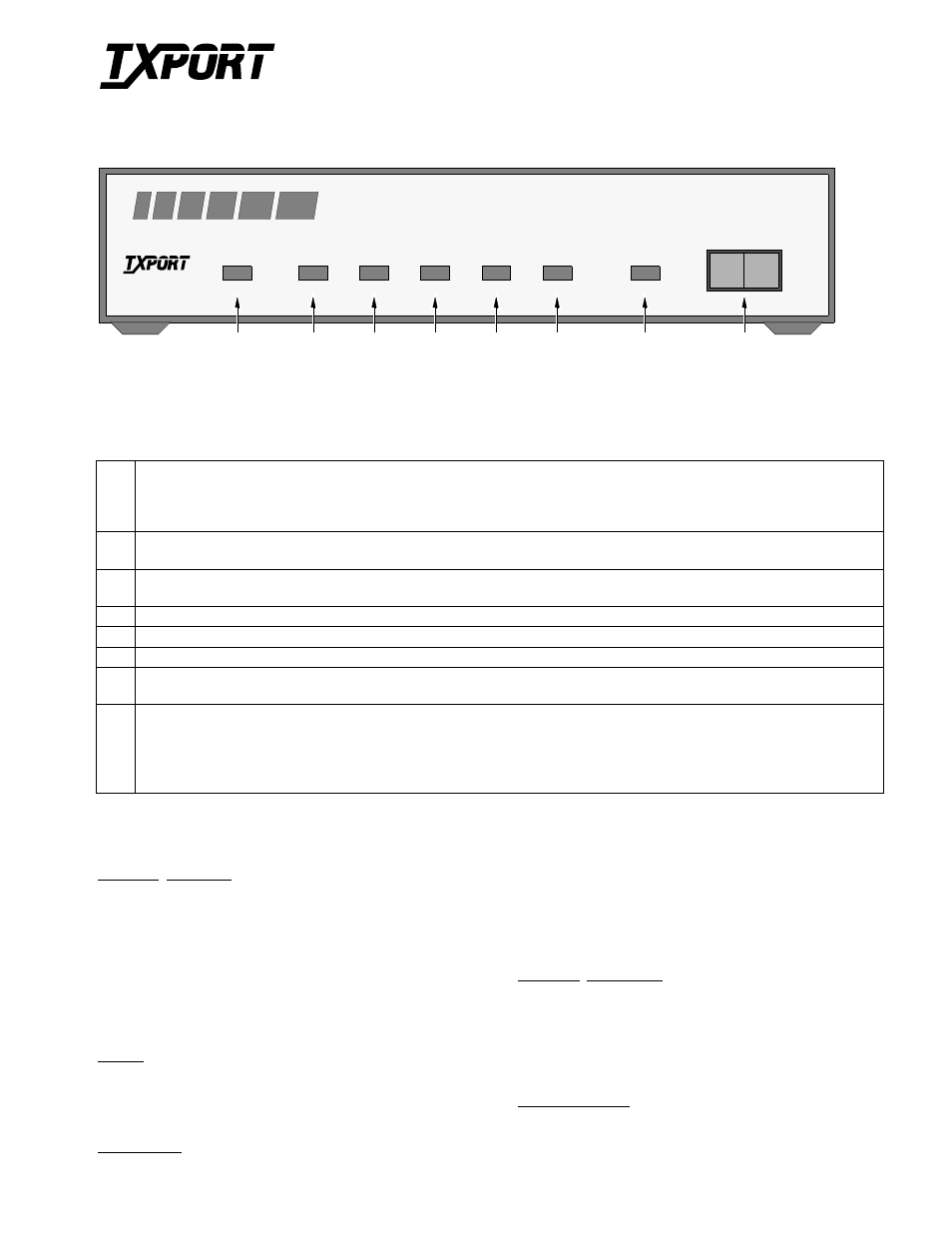
OOS: This three color Out Of Service LED indicates the DDS loop receiver’s operating status as follows:
Green: Indicates DDS signal at the receiver (either customer data or zero suppression).
Amber: Indicates DDS signal is still present, but received data is idle or out of service.
Red: Indicates an insufficient signal for the DDS receiver to operate properly.
2
SD: This green Send Data LED illuminates when the data lead is a mark and is Off when the data lead is a space.
Therefore, the LED will vary from full intensity to Off depending on the relative number of marks and spaces.
3
RD: This green Receive Data LED illuminates when the data lead is a mark and is Off when the data lead is a space.
Therefore, the LED will vary from full intensity to Off depending on the relative number of marks and spaces.
4
RTS: This green Request To Send LEDilluminates when circuit CA is in the On state at the DSU interface.
5
CTS: This green Clear To Send LED illuminatets when circuit CB is in the On state at the DSU interface.
6
RLSD: This green Receive Line Signal Detector LED illuminates when circuit CF is in the On state at the DSU interface.
7
TEST: This amber LED remains illuminated if the unit is in a test mode, either by manually depressing the loop switch or by receipt
of a test command from the facility. The LED turns red or green at the end of a V.54 test indicating the pass or fail state of the BERT.
8
Test Switch: This 3-position switch is used as follows: The LL position places the unit in a local loop mode. Data from the DTE is
looped back to the DTE. Data from the network is looped back to the network. The RL position initiates an automated V.54 remote
loop and BERT sequence of assigned data channels. The TEST LED will illuminate green if the test is successful (the far end unit
loops and returns the data error free with the V.54 code). If errors are detected, the TEST LED will illuminate red. The NORM
position deactivates the loop codes for normal operation.
OOS
1
(BA)
(BB)
(CA)
(CB)
(CF)
TEST
DSU/CSU
PRODUCTIVITY
SERIES
400
T
R
A
N
S
P
O
R
T
®
400 DDS DSU/CSU
Configuration Guide
45 -00061
3.0
Front Panel Description
TxPORT 400 Front Panel
T
R
A
N
S
P
O
R
T
®