Rear panel pinout, Specifications – Verilink 4010 Standalone (CG) Configuration/Installation Guide User Manual
Page 2
1
6
1
8
NETWORK
1
14
13
25
DTE
PORT
-48 VDC
ALARM/POWER
S1
S2
V
.35
S1, S2
RS232
S1
S2
V
.35
S1, S2
RS232
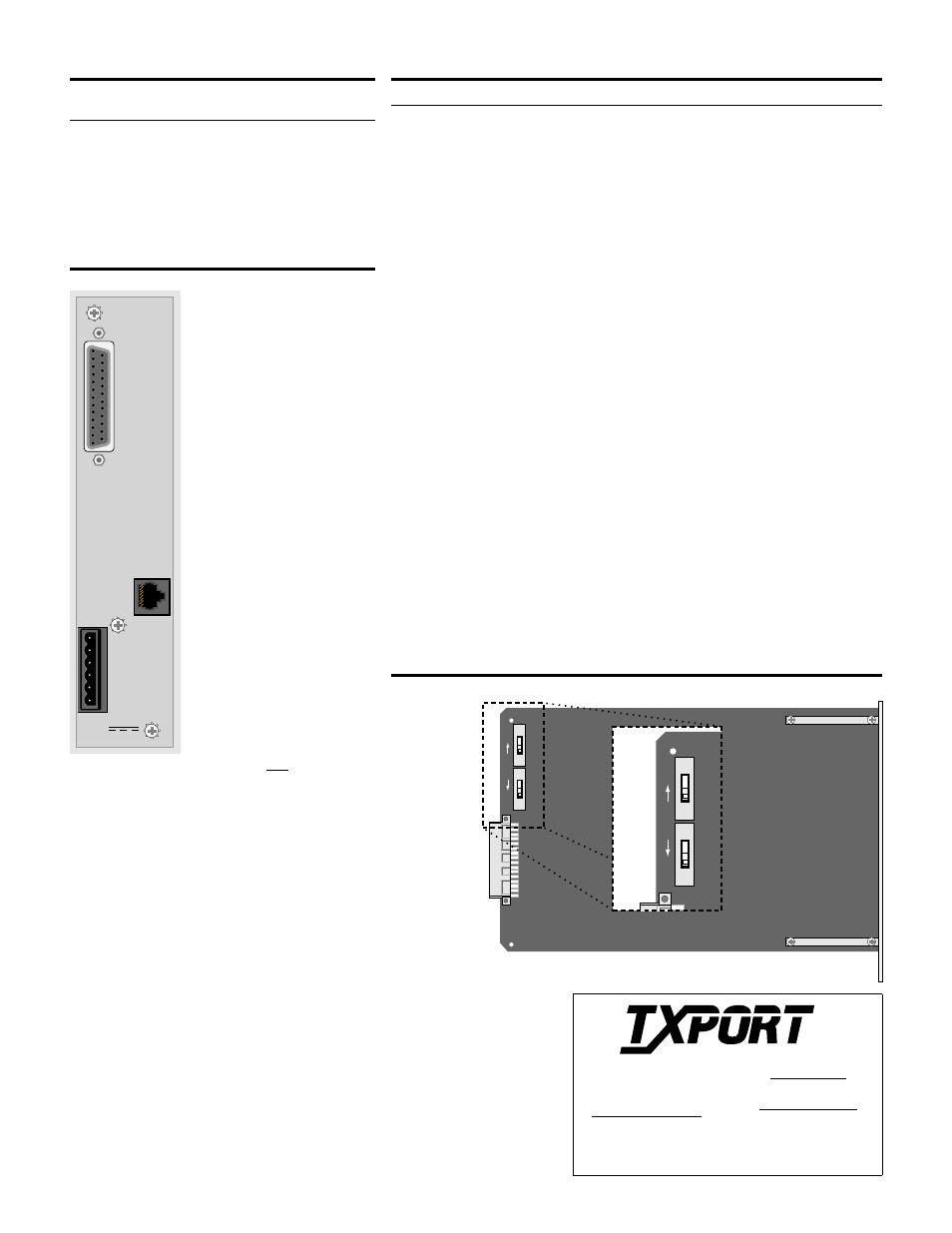
Rear Panel Pinout
Pin
NETWORK
(rear panel)
NETWORK
(9-1001-075-1)
ALARM/POWER
1
Data In (T)
Data Out (R1)
48 V Return
2
Data In (R)
Data Out (T1)
Signal Ground
3
not connected
not used
-48 VDC
4
Data Out (T1)
not used
Frame Ground
5
Data Out (R1)
not used
not applicable
6
not connected
not used
not applicable
7
Frame Ground
Data In (T)
not applicable
8
Frame Ground
Data In (R)
not applicable
Side View of the 4010
Switch S1 and S2
Access Procedure
1. Open the door.
2. Using both thumbs, gently
spread the plastic front panel
bezel near the LEDs until it
detaches from the front
panel.
3. Remove the screws from the
front panel.
4. Grasp the sides of the front
panel and remove the unit
from the housing.
5. Refer to Figure Side View of
the 4010 to set S1 and S2.
V.35 and RS-232 Interface
Ckt. RS-232 Signal Name - Function
DCE
101
1
Frame Ground - This circuit is used to terminate shields.
Gnd
102
7
Signal Ground - This circuit is used as the return reference for unbalanced signals.
Gnd
103
2 /14
Transmit Data - This input is used for synchronous TD from the DTE. It is
transmitted on the DDS side.
In
104
3 /16
Receive Data - This output is the data decoded from the incoming DDS
receive data.
Out
105
4
Request To Send - This input is a control line from the DTE, indicating data
is to be transmitted. When RTS is ON (space), the data transmitter, the zero
suppression circuitry, and the CTS are enabled. When RTS is OFF, the
transmitter sends idle code and the CTS is forced OFF.
In
106
5
Clear To Send - This output is a DCE response, indicating that either RTS is
ON or SW1 - 9, position B, is forcing RTS ON. When SW1- 8 is in position
B, RTS and RLSD must be ON for CTS to be ON.
Out
107
6
Data Set Ready - This output is ON when the unit is not in a test mode
(other than a V.54 test).
Out
109
8
Data Carrier Detect - This output is ON when the correct data or zero
suppression code is being received and DSR is ON. It is OFF when either
DSR is OFF, the DDS receiver has lost sufficient signal to operate for at
least one second, or the receiver has received OOS, OOF, idle, or loop
codes for about 20 U.I.
Out
113
24 /11
External Transmit Clock - This is the synchronous transmit clock input
from the DTE. When both SW1 -4 and SW1-5 are in the B position, this
clock controls the frequency of the DDS transmit clock and clocks circuit
103 (TD). When either SW1-4 or SW1-5 is in the A position, this input has
no effect on DDS operation.
In
114
15 /12
Transmit Clock - This output is supplied by the DCE as an external DTE
timing source. It is generated from the internal data clock or the far-end
transmit data. Not available if SW1-4 and S1-5 are in the B position.
Out
115
17 /9
Receive Clock - This clock output is the timing for the RD and is always
used to time the receive data. This clock is always derived from the DDS
receive data.
Out
Note: When two pins are listed, RS-232 only uses the first pin; V.35 uses both. All pins not
specified are open.
Specifications
Network Interface
Line Rate:
2.4, 4.8, 9.6,19.2, 28,
38.4, 56, and 64 kbps
Line Code:
AMI
Line Impedance: balanced 135
Ω
Input Signal:
+1 to - 40 dB
(ALBO)
Output Signal:
3.0 V (±15%) base-
peak into 135
Ω
,
1.5 V (±15%) at the
9.6 kbps line rate
Line Protection:
1000 V lightning,
input and output
Power
Power:
- 48 VDC (± 10%),
50 mA max,
3 watts, 10 BTU max
Connection: Terminal
strip
Mechanical
Mounting:
Standalone
Dimensions:
6.8" H, 1.75" W,
10.5" D
Weight:
2 lbs
Industry Standards
FCC Compliance: Part 15 Subpart B,
Class A
Part 68 Reg
Industry Canada:
CS03
US Safety:
UL 1459
Canadian Safety:
CSA22.2,No. 225-M90
AT&T TR 62310
AT&T TR 41450
Environmental
Operating Temp: 0° to 50°C
(32° to 122°F)
Storage Temp:
-20° to 85°C
(-4° to 185°F)
Humidity:
95% max
(non - condensing)
PRISM 4010
Rear Panel
127 Jetplex Circle
Madison, Alabama 35758
Sales and Marketing
800 - 926 - 0085
256-772-3770
Returns/RMA
800-926-0085, ext. 2227
Technical Support
800- 285 -2755
256- 772 -3770
T
R
A
N
S
P
O
R
T
®
Switch S1 and S2
V.35:
Set both switches Up.
RS-232:
Set both switches Down.