Verilink 4019 (WS) Configuration/Installation Guide User Manual
4019 csu plug-in installation worksheet
880-501285-001-B
April 1994
Page 1 of 1
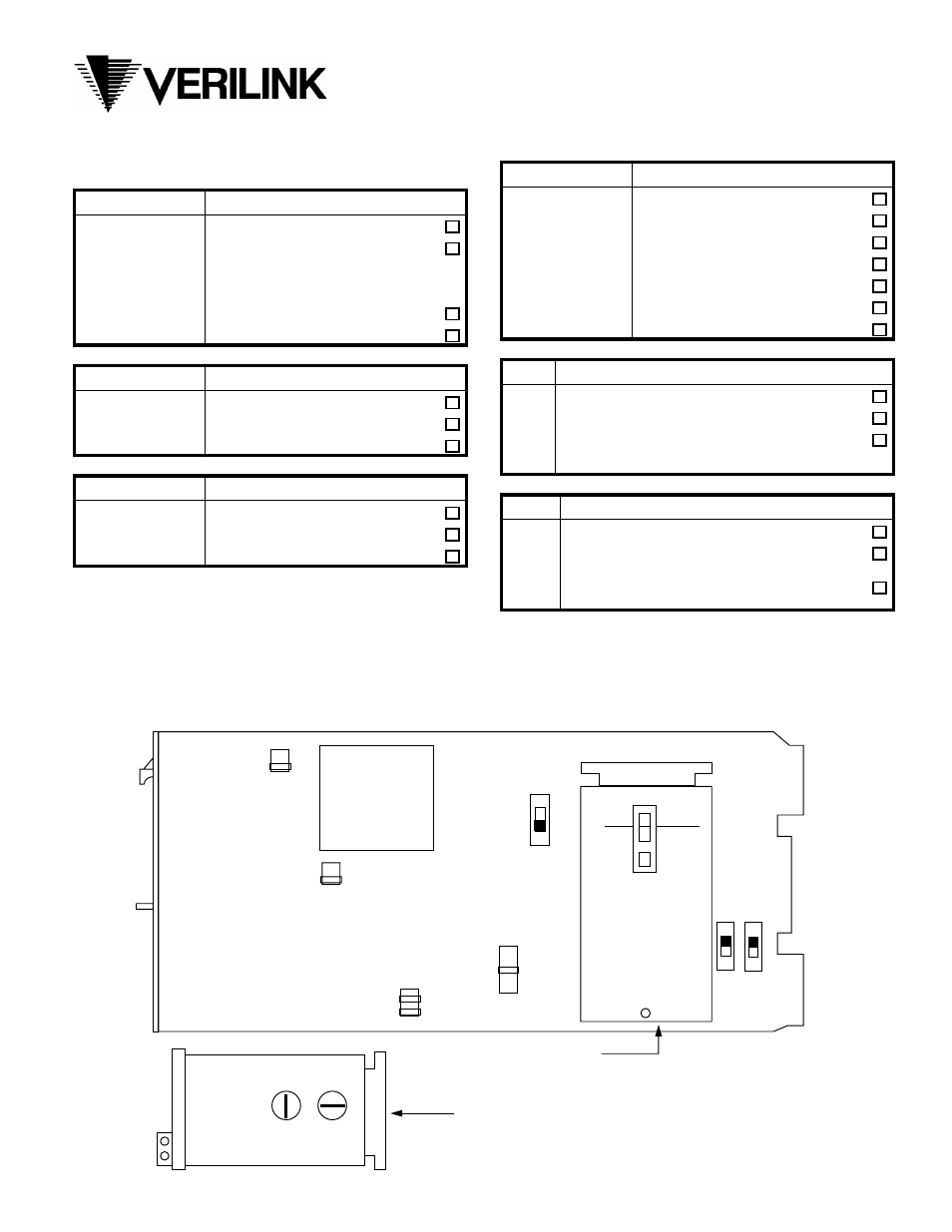
In each table, select the desired option in the rightmost
column.
WT-1 JUMPER
Keep-Alive
1 - 2*
AIS (All Ones) *
3 - 4
Loopback (ESS)
ZEROS LED turns on if exceeding:
5 - 6*
16 consecutive zeros *
7 - 8
50 consecutive zeros
WT-2 JUMPER
DTE RCV (Receive) Distance
1 - 2 *
0’ - 85’ *
3 - 4
85’ - 375’
5 - 6
375’ - 655’
WT-3 JUMPER
DTE XMT (Transmit) Distance
1 - 2 *
0’ - 85’ *
3 - 4
85’ - 375’
5 - 6
375’ - 655’
WT-4 JUMPER
BPV Threshold
1 - 2
10
-3
3 - 4
10
-4
5 - 6
10
-5
7 - 8 *
10
-6
*
9 - 10
10
-7
11 - 12
10
-8
13 - 14
10
-9
S1
S2
XMT (Artificial Line)
IN
IN
15dB:
0 - 1000 ‘ twisted copper
IN *
OUT *
7.5dB: 1000’ - 2000’ twisted copper *
OUT
OUT
0dB:
2000’ - 3000’ twisted copper or
local DS3 mux, radio, or other
equipment requiring DSX level
S3
Regenrator Critical Circuitry Power
LINE
T/STD
SP:
Span power *
LOCAL *
L/STD *
DL:
Local Power Dry Loop
(Loop any sealing current)
LOCAL
T/STD
WL:
Local Power Wet Loop
(CSU applies sealing current)
NOTES:
1. * = These are the factory defaults and are those most commonly used in the field.
2. For additional installation information, refer to manual Part No. 880-500497-001.
3. FCC Reg: GIC472-16731-DE-N
FIC: O4DU9-B
4. Telco jack: DA-15 or wire-wrap
....... .......
... ...
5
1
6
2
WT-3
S1
REGENERATOR
S2
OUT
IN
S3
13
1
14
2
WT-4
... ...
5
1
6
2
WT-2
LINE
LOCAL
STD
T
T
FL LOO
OPT
PWR
OPT
L
L
OS
STD
OS
FL OPT
PWR
OPT
L
T
OLD MODEL REGENERATOR
.... ....
7
1
8
2
WT-1
4019 CSU Plug-In
Installation Worksheet
C