Verilink 8100A (CG) Configuration/Installation Guide User Manual
8100a site controller, Front panel description, Specifications
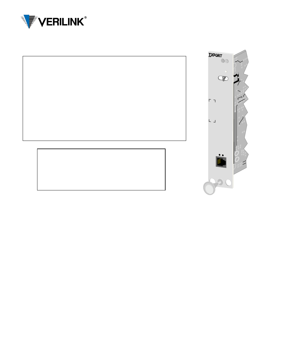
8100 A
SITE
CONTROLLER
STATUS
ACO
ACO SW
S
U
P
V
Front Panel Description
Status
The green LED lights when the unit is powered and operating normally .The
red LED lights if an alarm exceeding thresholds is detected or another type of
unit failure exists.
ACO
This yellow LED illuminates if the Alarm Cut-Off switch is placed in the left
(On) position. It indicates that the alarm relay contacts are disabled.
ACO SW
This switch controls the alarm relay circuitry. The left (On) position disables
the alarm relay contacts. The right (Off) position enables the contacts to
report alarm conditions.
Activity LEDs
These two small, recessed indicators are provided to indicate activity on the
NMS port.
SUPV
This 6- pin jack provides direct terminal access for controlling the unit and
gathering performance data. It functions as PORT 1, therefore you cannot
have Port 1 and the SUPV ports active at the same time. Refer to the Port 1
tables for configuring the bit rate and pinout settings for the SUPV port.
45-00098
3.0
8100A Site Controller
Configuration Guide
Specifications
SLIP Interface
Connection:
8-pin modular (RS-232)
Data Rate:
1.2, 2.4, 9.6, and 19.2 kbps
Compression:
SLIP compression
Ethernet LAN Interface
Net Protocol:
TCP /IP based networks
Access Method: Carrier sense multiple access with
collision detection (CSMA /CD)
Data Rate:
10 Mbps
Encoding:
Manchester
Connection:
Attachment Unit Interface (AUI)
DB-15 female with slide latch or
DB-15 female to 10Base-T
Compatibility:
AUI connects to media attach-
ment units (MAU) for 10BASE2,
10BASE5, and 10BASE- T (200
mA maximum current)
Token Ring LAN Interface
Net Protocol:
TCP /IP based networks
Data Rate:
4 or 16 Mbps
Connection:
8-pin modular
Compatibility:
Type 3 unshielded twisted pair
SNMP MIBS
MIB-II:
Device identification and LAN
interface performance data. All
applicable objects are maintained.
DS1/E1:
DS1/E1 network interface config-
uration and performance objects
are maintained per RFC 1406.
TxPORT:
Company information and enter-
prise TRAPs
DDS:
DDS equipment configuration
and maintenance objects.
Access Ports
Serial Ports:
2400, 9600, 19,200, and 38400
bps, 8 data bits, 1 stop bit, No parity
Modem Port:
(optional) 14,400 bps, V.42/V.42 bis
Power
DC Power:
-48 VDC (
±
10%) ,230 mA max,
11 Watts, 38 BTU max.
Connection:
The module unit connects to and
receives power from a 1051 chas-
sis backplane. The standalone
unit uses a terminal block.
Alarm Contacts: 30 Volt and 1 Amp maximum
Mechanical (standalone model)
Mounting:
Desktop, wall, horizontal or ver-
tical rack
Dimensions:
Width - 1.72 inches (4.37 cm)
Height - 6.8 inches (17.27 cm)
Depth - 10.5 inches (26.67 cm)
Weight:
2 pounds (0.91 kg)
Environmental
Operating Temp:0
°
to 50
°
C (32
°
to 122
°
F)
Storage Temp:
-20
°
to 85
°
C (- 4
°
to 185
°
F)
Humidity:
95% max (non - condensing)
Industry Listings
FCC:
Part 15 Subpart B, Class A
Part 68 Cert:
DWEUSA-75322-FA-E
Modem: XE1414V
NRTL Cert:
LR 98859
IC /CSO3: 1653
6223
A
Internet:
RFC 1155 (SMI)
RFC 1157 (SNMP)
RFC 1213 (MIB - II)
RFC 1406 (DS1/E1 MIB)
RFC1055 (SLIP)
Ethernet:
ISO /IEC 8802 - 3
Important Notice:
When installing the 8100A Site Controller as a rack-
mounted unit, it must be installed using thread-
forming screws with external tooth lock washers in
order to meet GR-1089 grounding requirements.