Verilink APS Card Replacement (CG) Configuration/Installation Guide User Manual
Page 4
TxPORT Customer Service
127 Jetplex Circle
Madison, Alabama 35758
Customer Service
800-926-0085, ext. 227
Product Technical Support
(8 a.m. to 5 p.m. Central Time)
800- 285-2755 or
205- 772-3770
Emergency After Hours
800- 285-2755
E-Mail (Internet Address):
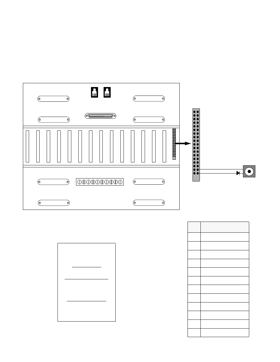
J5
REMOTE ALARMS/CONTROL
J6
J7
J1
J2
C14
C13
C12
C11
C10
C9
C8
C7
C6
C5
C4
C3
C2
C1
35
C15
J8
J9
J3
J4
36
2
1
Figure 1
1050 Chassis Rear View
TB1
Pin
C15 Function
1
-48 VDC - Primary
5
48 V RTN
9
-48 VDC - Secondary
18
Alarm NC
19
Alarm NO
20
Alarm Common
29
NMS In
30
NMS Out
34
NMS Ground
31
-48V DC, Secondary Bus
33
-48 Return, Return
35
-48V DC, Primary Bus
35
C15
36
2
1
Spare
Pin 33, White Jumper
Pin 35, Black Jumper
Notes for wiring connections to attach exter-
nal -48 VDC and Return to APC shelf.
1. Attach slide-on connector (black lead) to
wire wrap pin 35 of connector C15. Attach
other end to -48VDC lead of 23 A fuse.
2. Attach slide-on connector (white lead) to
wire wrap pin 33 of connector C15. Attach
other end to -48 Return lead of 23 A fuse.
3. Make sure fuse rating of 23 A fuse is 3
amps, slow blow.
4. After making connections fuse 23 A posi-
tion with 3 amp slow blow fuse.
-48 VDC
-48 Return
23 A fuse