Verilink FSD EPROM Replacement (CG) Configuration/Installation Guide User Manual
Fsd/fst, Eprom replacement instructions
FSD/FST
45-00145
1.0
CAUTION: An open module is susceptible to damage caused by static electricity. Use ESD
(electrostatic discharge) precautionary measures.
1. Unplug the unit and remove all the cables.
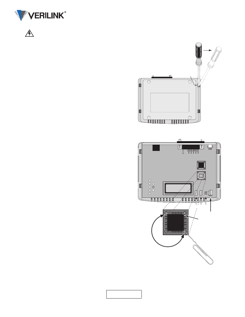
2. Release the latches holding the cover of the base by first
finding the four 3/8-inch openings as shown. Insert a
flat blade screwdriver in the opening 1. Apply pressure
away from the unit while partially separating the cover
from the base with the other hand.
3. Repeat Step 2 for opening 2.
4. Repeat Step 2 and Step 3 for the other side of the unit.
5.
Remove the cover from the unit and place the unit on its base.
6. Find the sockets holding U4 and U5.
7. Remove IC U4 from its socket by inserting the
straightened end of a jumbo paper clip or small
screwdriver in one of the slotted corners of the socket
and prying gently. Repeat for the opposite corner of the
socket until the ICs can be removed. Take care not to
damage the sockets or the circuit board.
Note that the ICs have three square corners and one angled
corner.
8. Align the angled corner of the Install the new U4
(labeled 0100) in its socket by placing the part over the
socket so the angled corners match.
9. Center U4 in the socket and press down gently until the
IC seats. The top of a properly seated IC is level with
the top of the socket.
10. Repeat Step 6 through Step 9 to install the new U5
(labeled 0101).
11. Reinstall the cover to the base by first removing the
switch caps from the switches.
12. Check that the circuit board and rear panel are still in
the base and the connectors protrude through the panel.
13. Align the cover over the base unit making sure that the
rear panel is on the inside of the cover.
14. Use both hands to press down on the cover until it snaps
into place.
15. Reinstall the switch caps through the switch openings
and press down on the caps to seat them on the
switches.
16. Attach all cables and the power transformer.
17. Perform a hardware reset to ensure proper operation. To execute a hardware reset, press the Select and Exit
buttons while applying power to the unit and hold them for five seconds. A hardware reset restores the unit
to factory default settings just like a Restore Factory Settings command. The following screen appears as the
unit comes out of hardware reset.
Opening #1
2
3
4
Use caution when prying
or you will be crying!
Applying too much pressure
may break plastic components.
Switches
Switch Cap
Angled Corner
U4
U5
FRAME START DDS
***UNIT RESET***
EPROM Replacement Instructions