Verilink PRISM 4001 (CG) Configuration/Installation Guide User Manual
Prism 4151, Configuration guide, Front panel
T
R
A
N
S
P
O
R
T
®
PRISM 4151
Configuration Guide
45-00105
3.0
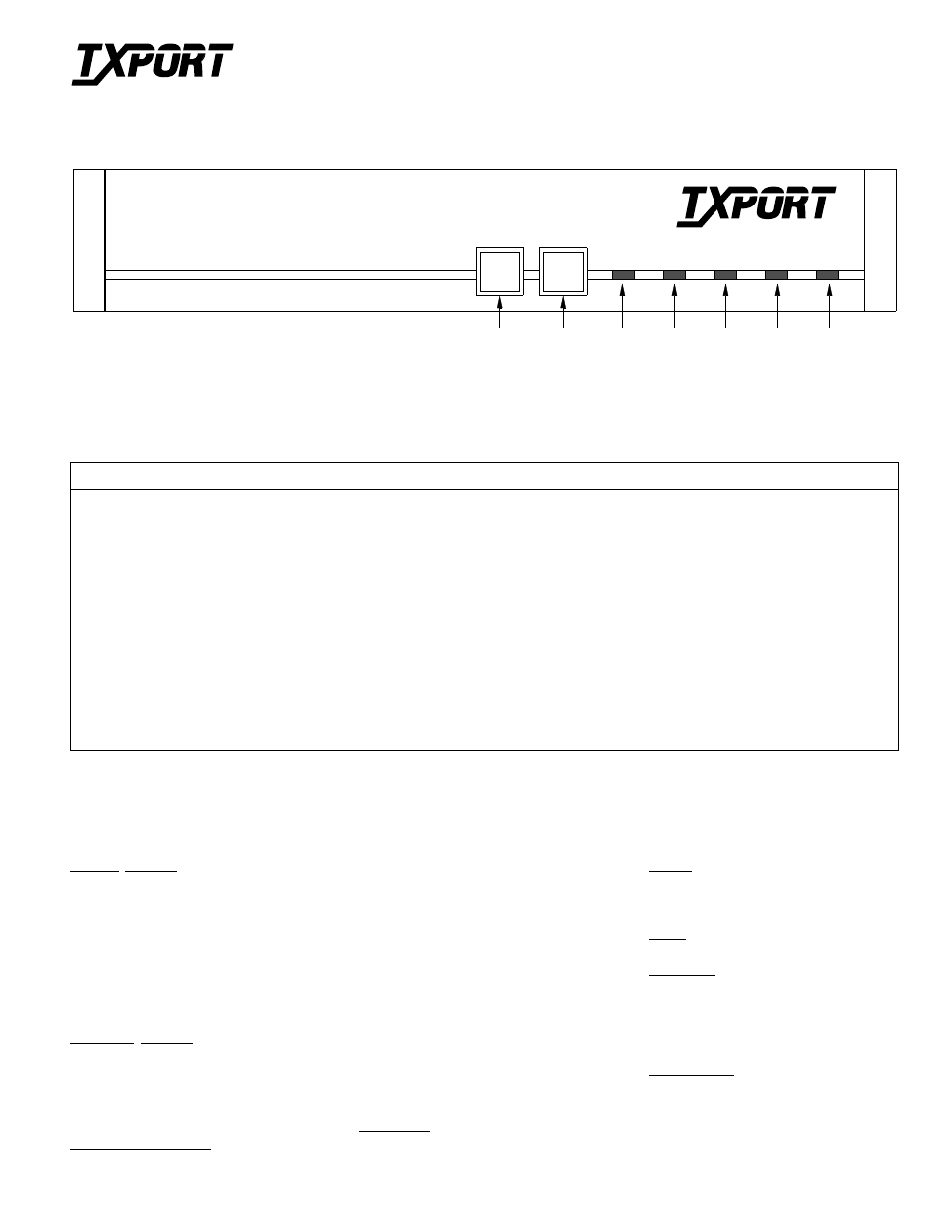
Front Panel
Network Interface
Line Rate:
56 and 72 kbps
Input Signal:
0 to - 45 dB ALBO
Connection:
RJ-48C jack
Output Signal:
3.32 V (
±
10%) base- peak into
135
Ω
with protection per 62310
Transient Voltage: 1000 V protection, fused in /out
Jitter Control:
per 62310
Timing Source:
Internal, recovered line clock,
external DTE
Equipment Interface
Data Rate:
Synchronous 56K DDS I , 64K
DDS II
Antistream Timer: Off, 10, 30, or 60 seconds
DTE Clocking:
Internal or External
DTE Connection: 34-pin V.35 (CCITT)
Management Interfaces
Supervisory Port
Connection:
8 -pin modular (RS-232)
Data Rates:
19.2 kbps
SLIP Port
Connection:
8 - pin modular (RS-232)
Data Rates:
1.2, 2.4, 9.6, and 19.2 kbps
SNMP /Telnet Ethernet (option)
Connection:
8 - pin modular (RJ-45)
Network Protocol: TCP /IP based networks
Data Rate:
10 Mbps
Compatibility:
10BASE- T, ISO.IEC 8802-3
SNMP /TELNET/Token Ring
Connection:
8 - pin modular (RJ-45)
Network Protocol: TCP /IP based networks
Data Rate:
16 Mbps
Compatibility:
Type 3 UTP, ISO/IEC 8802-5
Diagnostics
Loopbacks:
V.54 (receive and send), alternat-
ing loop, latching loop
BERT:
511 pattern
Alarms
Activation:
Programmable thresholds
Reporting:
Front panel LEDs, call on
alarm (COA), SNMP traps
Power
115 VAC:
100 mA, 12 W max, 30 BTU max
Mechanical
Mounting:
Desktop or rack
Dimensions:
12 inches (30.48 cm) wide
2 inches (5.08 cm) high
9 inches (22.86 cm) deep
Weight:
4 pounds (1.814 kg)
Environmental
Operating Temp: 32
°
to 122
°
F (0
°
to 50
°
C)
Storage Temp:
-4
°
to 185
°
F (-20
°
to 85
°
C)
Humidity:
95% maximum, non-condensing
ALARM
NET
LOOP
TEST
TEST
LOOP
POWER
2
1
4
3
5
6
7
PRISM 4151
T
R
A
N
S
P
O
R
T
®
Specifications
Front Panel Description
Index
Item Function
1 TEST
(button)
When this button is pushed once, the unit transmits five seconds of V.54 loop code out to the network. The indicator blinks amber
during transmission of the loop code. When the V.54 loop sequence is finished, a 511 BERT pseudo rendom sequence is
transmitted. The received pattern is compared and if it is error free, the TEST indicator remains green. If pattern errors are
detected, the TEST indicator turns red for a minimum of one second. If the TEST button is pushed again, the unit transmits five
seconds of V.54 loop down code and returns to normal operating mode. The TEST indicator is then turned off.
2 LOOP
(button)
When this button is pressed once, the unit activates a line loopback, looping the network receive data back to the network, and
looping the data from the DTE ports back to the DTE. The LOOP indicator is lit while the unit is in loop. If pushed again, the
unit clears the loop and turns off the LOOP indicator.
3
TEST
This 3-color LED is green when BERT is on with no errors. It flashes amber when the unit is transmitting loop or unloop code.
It is red when the BERT is on and is receiving errors or is out of pattern sync.
4
LOOP
This amber LED illuminates when the unit is in any loop condition.
5
NET
This 3-color LED illuminates green when the unit is in frame sync. It is red when the unit is out of sync and/or Loss of Signal.
6
ALARM This red LED illuminates when the unit is in an active alarm condition.
7
POWER This green LED illuminates when power is applied to the unit.