Verilink PRISM 3301 Download (CG) Configuration/Installation Guide User Manual
Txport 4001 dds csu/dsu, Configuration guide (chassis version)
T
R
A
N
S
P
O
R
T
®
Dialing:
Numbers programmed and stored in
4001 and transmitted to backup unit
by inband AT commands
Restoral:
Manual or automatic restoral to leased
line service
Mechanical
Mounting:
Fits TxPORT 1051 chassis
Dimensions:
1.72” W, 6.8” H, 10.5” D (unit)
17.2” W, 7” H, 10.5” D (chassis)
Environmental
Operating Temp:
0° to 50°C (32° to 122°F)
Storage Temp:
-20° to 85°C (-4° to 185°F)
Humidity:
95% maximum (non-condensing)
Compatibility
AT&T TR 62310
AT&T TR 41450
Industry Listings
FCC Compliance:
Part 15 subpart B, Class A and Part 68
NRTL: UL
1459
CSA Certified:
Pending
DOC /CSO3:
Pending
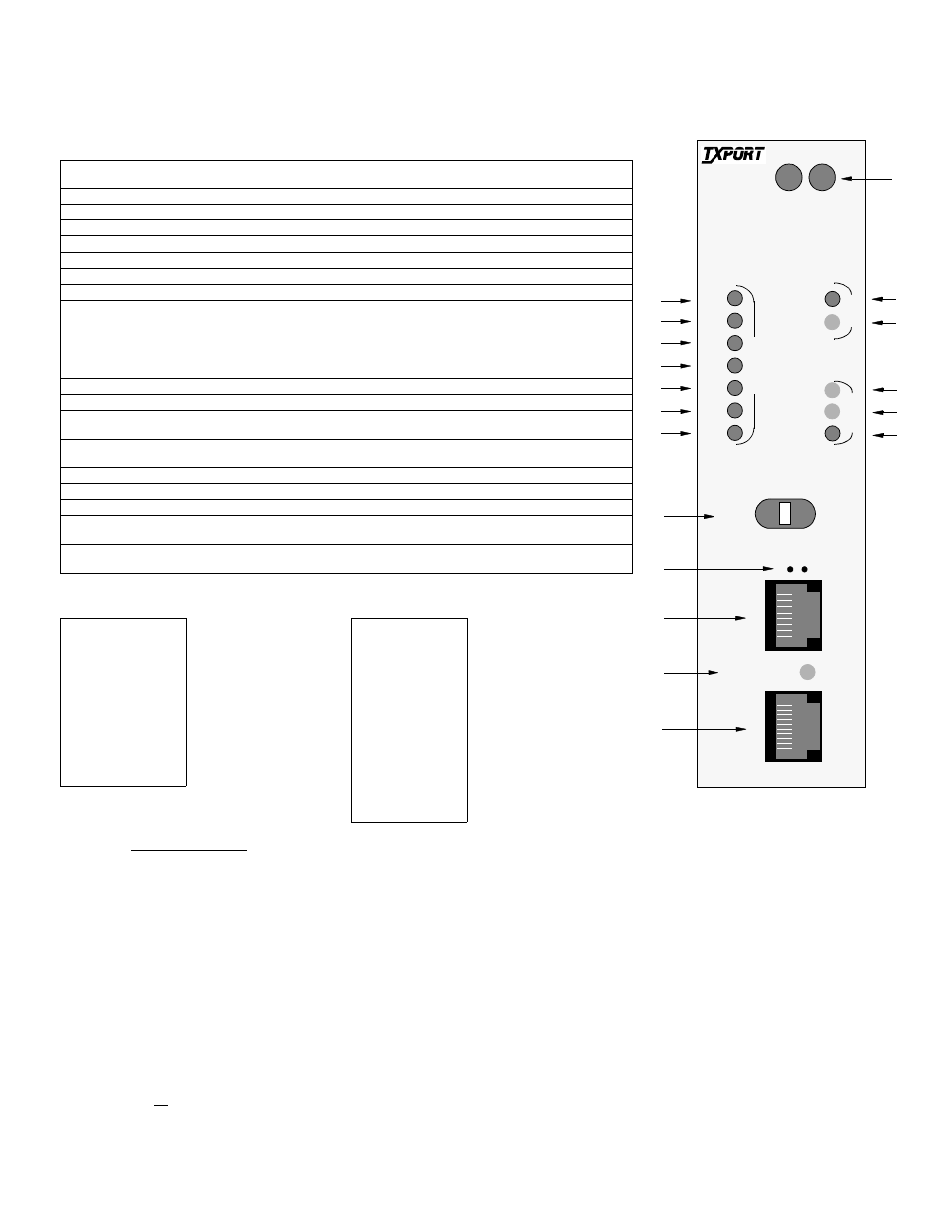
1
Status: The green LED lights when the unit is powered and operation is normal. The red LED lights if an alarm
exceeding thresholds is detected or for other unit failure.
2
TD: This green LED lights during a mark condition on the high-speed transmit data line.
3
RD: This green LED lights during a mark condition on the high-speed receive data line.
4
RTS: This green LED lights when the request-to-send signal is active.
5
CTS: This green LED lights when the clear-to-send signal is active.
6
DCD: This green LED lights when the data-carrier-detect signal is active.
7
DTR: This green LED lights when the data-terminal-ready signal is active.
8
DSR: This green LED lights when the data-set-ready signal is active.
9
Test Switch: This switch (FAR/LOC) is used for local testing. When in the FAR position, the unit sends five seconds
of the V.54 loop pattern, then switches to the 511 pattern. When transmitting a test pattern, the TEST LED is lit con-
tinuously. The ERR LED lights for one second when a bit error or sync loss on the returned data is detected. After the
FAR test has been completed, the ERR LED is Off for “passed” or On for “failed.” When in the center position, the
unit sends five seconds of V.54 loopdown code and then returns to its normal operating mode. When in the LOC posi-
tion, the unit performs a network LLB and the LOOP LEDs light.
10
Activity Indicators: This two small, recessed LEDs indicate supervisory and network manager port activity.
11
SUPV: This supervisory jack provides direct terminal access for controlling the unit. Refer to the pinout table below.
12
DBU Active: This yellow LED lights when the dial backup is active. It blinks when a dial backup connection is being
established.
13
DBU: This 10-pin jack provides a sync or async interface for external dial backup equipment and also provides a con-
nection to the internal DBU, when installed.
14
LOS: This LED lights with a loss of signal from the DDS network.
15
OOS: This LED lights when an out-of-service code is detected.
16
LOOP: This LED lights continuously when the network interface is in a line loopback.
17
TST: This LED lights continuously whenever the BERT pattern generator is active, including during LOOP,
UNLOOP, and FAR test.
18
ERR: This LED lights when BERT pattern errors are detected. At the end of a FAR test, it indicates the results of the
test as long as the FAR/LOC switch remains in the FAR postion.
SPECIFICATIONS
Network Interface
Service Types:
DDS-I conforming to TR 62310 and
TR 41450
Operating Modes:
Full Duplex, Point-to-Point, and
Multi-Point
Line Rates:
2.4, 4.8, 9.6, 19.2, 38.4, and 56 kbps
(64 kbps for LDM only)
Loop Range:
Up to 45-dB loss
Timing Source:
Network, DTE, Internal
Equipment Interface
Sync Data Rates:
2.4, 4.8, 9.6, 19.2, 38.4, 54, 56, 62,
and 64 kbps
Async Data Rates:
2.4, 4.8, 9.6, 19.2, 38.4, and 57.6 kbps
Rate Adaptation:
Adapts subrate data port speeds to 56-
or 64-kbps line rate
Anti-Stream Timer:
Up, 10, 30, or 60 seconds
DTE Connection:
DB-25 (PN 1051-2) or V.35 connec-
tor (PN 1051-3). Selection depends on
chassis model.
DTE Interface:
RS-232 or CCITT V.35
Power
-48 VDC:
130 mA, 20 W, 73 BTU maximum
Diagnostics
Status Indication:
Front panel LEDs
Terminal interface on SUPV port
Telnet session or SNMP management
via TxPORT 8100A Site Controller
Loopbacks:
CSU, V.54 (receive and send) front
panel switch for loop activation
BERT:
511 pattern
Configuration
Card Edge:
Four DIP switches, two slide switches
SUPV Port:
(Supervisory port to terminal interface)
Connection:
8-pin modular (RS-232)
Data Rates:
1.2, 2.4, 9.6, and 19.2 kbps
Management:
Terminal interface session Telnet ses-
sion via 8100A SNMP management
system via 8100A
Dial Backup
Connection:
RS-232, 10-pin modular
Backup Service:
PSTN or ISDN (external) optional
14.4 modem (internal)
Configuration:
Information for backup unit is stored
in 4001 and transmitted to backup unit
by inband AT commands
DBU Port Pinout
Pin
Signal
1
Rx Clock Out
2
DTR Out
3
RTS Out
4
Frame Ground
5
Data Out
6
Data In
7
Signal Ground
8
CTS In
9
DCD In
10
Tx Clock Out
SUPV Port Pinout
Pin
Signal
1
DCD Out
2
CTS Out
3
Frame Ground
4
Data Out
5
Data In
6
Signal Ground
7
RTS In
8
DTR In
17
7
6
5
4
18
16
15
14
TxPORT 4001 DDS CSU/DSU
Configuration Guide (chassis version)
Front Panel Description
LOS
LOC
FAR
OOS
LOOP
TST
N
E
T
ERR
D
T
E
TD
RD
RTS
CTS
S
U
P
V
8
1
DCD
DTR
DSR
T
S
T
D
B
U
10
1
DBU ACTIVE
STATUS
1
2
3
8
9
10
12
11
13
4001
DDS
CSU/DSU