Verilink PRISM 3301 (CG) Configuration/Installation Guide User Manual
Prism 3301, Configuration guide, Prism 3301 rear panel
PRISM 3301
Configuration Guide
45- 00109
2.0
T
R
A
N
S
P
O
R
T
®
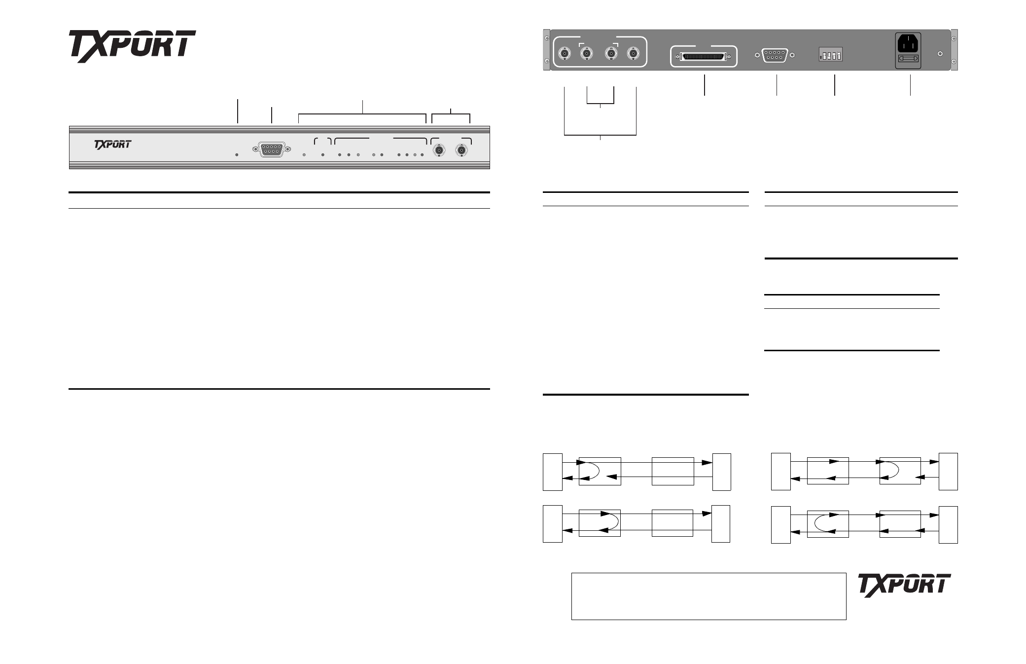
PRISM 3301 Rear Panel
®
®
PRISM 3301
POWER
TEST
BPV
YEL
YEL
TX
LOSS
RX
AIS
AIS
TX
RX
MONITOR
NETWORK
DTE
SIG FRM
PAR
ERR
REM
PAR
ERR
CLOCK
LOSS
LOCAL ACCESS
Power
LED
ASCII
Terminal
Interface
Test & Alarm
LEDS
BNC
Access
Jacks
O
N
1
2
3
4
USE ONLY WITH 250V FUSE
NETWORK
IN
OUT
IN
OUT
PRIMARY
SECONDARY
PRIMARY
DTE
NETWORK
MGMT
(RS232)
CONTROL
SWITCH
ON
OFF
CAUTION:
TO PREVENT RISK OF
FIRE USE SAME TYPE\
RATING OF FUSE
110V, .5A
50/60HZ
GND
250V, 2A
Primary Power
Receptable
4-Pin
DIP Switch
RS-232
Serial Comm.
Interface with
Embedded SNMP
High-Speed
Serial Interface
(HSSI)
DTE Interface
To
Hot-Standby
Unit
T3 Network Interface
IN
IN
OUT
OUT
Sales and Marketing
888-489-7678
256-772-3770
Technical Support
800-285-2755
256-772-3770
Returns/RMA
888-489-7678, ext. 2282
127 Jetplex Circle
Madison, Alabama 35758
Specifications
Network Interface
Line Rate:
44.736 Mbps (±20 ppm)
Line Framing:
C-Bit parity framing
Line Code:
B3ZS (bipolar with 3-zero
substitution)
Line Impedance:
75
Ω
(5% resistive)
Equipment Interface
DTE Port:
High-speed Serial Inter-
face (HSSI) 50-pin Am-
plimite shielded (female)
Data Rates:
3.16, 6.32, 12.36, 18.95,
25.26, 31.58, 37.89, and
44.21 Mbps
Management Interfaces
Connection:
Two female 9-pin, D-type
(RS-232)
Compatibility:
EIA /TIA - 574
Data Rates:
1.2, 2.4, 4.8, 9.6,
and 19.2 kbps
Diagnostics
Performance:
Monitoring per AT&T
TR 54014
Alarm Report:
Time, Date, and Type
History:
100 entries
Loopbacks:
local line loopback, local
DTE loopback, remote line
loopback, and remote line
loopback (far end)
Alarms
Activation:
Enable/Disable
Reporting:
Front panel LEDs, audible
alarm, 100-message alarm
queue in memory
Power
110 VAC:
Less than 7 watts
Mechanical
Mounting:
Desktop and vertical rack
Dimensions:
17" (43.18 cm) high
1.75" (4.45 cm) wide
12" (30.48 cm) deep
Weight:
6.4 pounds (2.10 kg)
Environmental
Operating Temp:
32
°
to 122
°
F (0
°
to 50
°
C)
Humidity:
10 to 90% (noncondensing)
Industry Standards
FCC Compliance: Part 15 Class A, Subpart B
U.S. Safety:
UL 1459 2
nd
Edition/
UL 1950 2
nd
Edition
Canadian Safety: CSA C22.2 No. 225-M90
CSA C22.2 No. 950-M89
Compatibility
AT&T TR 54014: May 1992
PRISM 3301 Front Panel
Item Function
Power
This green LED illuminates when there is power to the unit and the power supply is operating normally.
Test
This amber LED illuminates when the unit is in loopback or loopup test modes.
Clock Loss
This red LED illuminates when the unit stops receiving the transmit timing clock sent by the DTE.
BPV
This red LED illuminates when a BPV rate greater than 10
-6
ocurs over a one second interval.
PAR ERR
This red LED illuminates when the C-bit parity error rate exceeds 10
-6
for 10 minutes.
REM PAR ERR This amber LED illuminates when the remote unit C-bit parity error rate exceeds 10
-6
for 10 minutes.
TX YEL
This red LED illuminates when a yellow alarm is present.
TX AIS
This red LED illuminates when a signal is transmitted in place of the normal signal to maintain tranmission continuity and
to indicate to the destination terminal that there is a transmission fault at or upstream from the source terminal.
LOSS SIG
This red LED illuminates when a signal loss condition of 128 consecutive zeros is encountered.
LOSS FRM
This red LED illuminates when three errors in 16 conseutive F-bits are detected or when there is an error in the M-bit pat-
tern in two out of three (or two out of four) consecutive M-frames.
RX YEL
This red LED illuminates when a yellow alarm is present.
RX AIS
This red LED illuminates when a signal is transmitted in place of the normal signal to maintain tranmission continuity and
to indicate to the destination terminal that there is a transmission fault at or upstream from the source terminal.
DTE Interface
Pin (+) Pin (
−
) Symbol
Circuit Name
Direction
1
26
SG
Signal Ground
2
27
RT
Receive Timing
Output
3
28
CA
DCE Available
Output
4
29
RD
Receive Data
Output
5
30
LC
Loopback Circuit C
Output
6
31
ST
Send Timing
Output
7
32
SG
Signal Ground
8
33
TA
DTE Available
Input
9
34
TT
Terminal Timing
Input
10
35
LA
Loopback Circuit A Input
11
36
SD
Send Data
Input
12
37
LB
Loopback Circuit B
Input
12
38
SG
Signal Ground
14–18
39– 43
Reserved
19
44
SG
Signal Ground
20–23
45– 48
Reserved
24
49
TM
Test Mode
Output
25
50
SG
Signal Ground
Network Mgmt and Local Access Interfaces
Pin Signal
Name
Input/Output
1
DCD
Data Carrier Detect
Input
2
RD
Receive Data
Input
3
TD
Transmit Data
Output
4
DTR
Data Terminal Ready Output
5
GND
Control Switch (S1)
Switch
Function
On
Off
S1-1
Power Up
Cold Reboot Normal
S1-2
Program Mode
Flash
S1-3
Reserved
S1-4
Alarm Indicator Silent
Audible
DTE
DTE
Local 3301
Remote 3301
DTE
Local 3301
Remote 3301
DTE
DTE
DTE
Remote 3301
Local 3301
Local DTE Loopback
Local Line Loopback
Remote Line Loopback (Request/End)
DTE
DTE
Remote 3301
Local 3301
Remote Line Loopback (Set Clear)
Loopback diagrams are viewed from the local PRISM 3301
Loops