Verilink PRISM 4101 (IG) Configuration/Installation Guide User Manual
Prism 4101, Configuration guide, Specifications
PRISM 4101
Configuration Guide
45-00137
1.0
Specifications
Network Interface
Service Type:
DDS-I conforming to TR
62310
Operating Modes: Full duplex, point-to-point,
multi-point
Line Rate:
2.4, 4.8, 9.6, 19.2, 38.4, 56,
and 72 kbps
Loop Range:
Up to 45 dB of loss
Line Connection: RJ-48S jack, 8-pin modular
Timing Source:
Network, DTE, or Internal
Equipment Interface
Sync Data Rates: 2.4, 4.8, 9.6, 19.2, 38.4, 54, 56,
62, and 64 kbps
Async Data Rates: 2.4, 4.8, 9.6, 19.2, 38.4, and
57.6 kbps
Rate Adaptation:
Adapts subrate data port
speeds to 56 or 64 kbps line
rate
Antistream Timer: Off, 10, 30, or 60 seconds
DTE Connection: 34-pin V.35 (ITU) and 25-pin
RS-232D (EIA)
Supervisory Port
Connection:
8 -pin modular (RS-232)
Data Rates:
1.2, 2.4, 9.6, and 19.2 kbps
SLIP Port
Connection:
8 -pin modular (RS-232)
Data Rates:
1.2, 2.4, 9.6, and 19.2 kbps
Ethernet (option)
Connection:
8 -pin modular
Network Protocol: TCP/ IP based networks
Data Rate:
10 Mbps
Compatibility:
10BASE -T, ISO/IEC 8802-3
Token Ring (option)
Connection:
8 -pin modular (RJ-45)
Network Protocol: TCP/ IP based networks
Data Rate:
4 or 16 Mbps
Compatibility:
Type 3 UTP, ISO/IEC 8802-5
Dial Backup
Connection:
RS-232, 10-pin modular
Backup Service:
PSTN or ISDN, sync or async
Configuration:
Information for backup unit is
stored in the PRISM 4101 and
transmitted to backup unit by
inband AT commands
Dialing:
Numbers programmed and
stored in the PRISM 4101 and
transmitted to backup unit by
inband AT commands
Restoral:
Manual or automatic restoral
to leased line service
Diagnostics
Loopbacks:
CSU, V.54 (send and receive)
BERT:
511 pattern
Power
115 VAC:
150 mA, 14 W max, 47 BTU
max
Mechanical
Housing:
Plastic standalone case
Mounting:
Desktop or horizontal rack
Dimensions:
12 inches (30.40 cm) wide
2 inches (5.08 cm) high
9 inches (22.86 cm) deep
Weight:
4 pounds (1.814 kg)
Environmental
Storage Temp:
- 4
°
to 185
°
F (- 20
°
to 85
°
C)
Operating Temp:
32
°
to 122
°
F (0
°
to 50
°
C)
Humidity:
95% maximum (non-
condensing)
Compatibility
TR 62310:
November 1987
TR 41450:
November 1981
Internet Standards: RFC 1157 (SNMP)
RFC 1155 (SMI)
RFC 1213 (MIB-II)
RFC 1055 (SLIP)
Enterprise TxPORT MIB
Enterprise DDS MIB
Industry Listings
FCC Compliance: Part 15 Class A, Subpart B,
Part 68
U.S. Safety:
UL 1950, 3
rd
Edition
Canadian Safety: CSA C22.2 No. 950-95
Industry Canada:
CS03, Issue 8 (CSU/DSU only)
Button Function
EXIT
SCROLL
SELECT
Returns you to the previous menu. Once you are at the main menu, the Exit button closes your interface session. Modifications to some
menus do not take effect until you exit from that menu.
Allows you to toggle through a list of options for each menu item selected.
Allows you to choose a specific or item (similar in functionality to the Return key). When you press the Select button on a user selectable
item, the selected parameter becomes the new setting and you are returned to the previous menu.
LED
Function
BACKUP
TEST
ALARM
POWER
Illuminates amber when the DBU is actively transferring data. Blinks amber when a DBU connection is being established or terminated.
Illuminates amber when the unit is transmitting loop code, unloop code or the 511 BERT pattern in a loop mode such as line, data, V.54, etc.
Illuminates red when the unit is in an active alarm condition.
Illuminates green when power is applied to the unit.
PRISM 4101 Front Panel
T
R
A
N
S
P
O
R
T
®
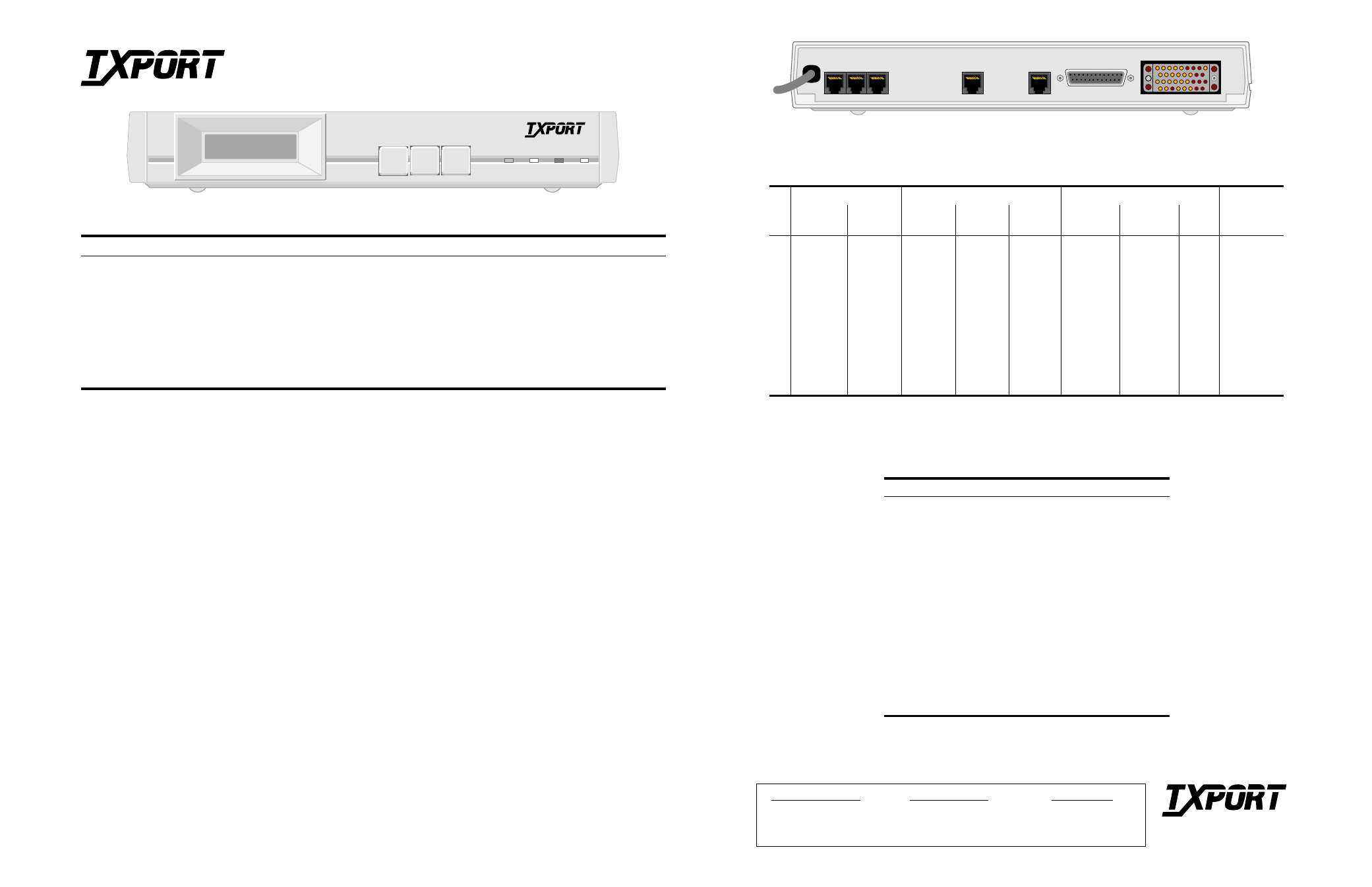
PRISM 4101 Rear Panel
T
R
A
N
S
P
O
R
T
®
Sales and Marketing
888-4TxPORT
256- 772-3770
Technical Support
800-285-2755
256-772-3770
Returns/RMA
888-4TxPORT, ext. 2282
127 Jetplex Circle
Madison, Alabama 35758
Rear Panel Pinouts
Pin
LAN
SLIP/SUPV
DBU
DDS
Ethernet
Token Ring
Connector
Pinout
PC
Connector
Modem
Connector
Connector
Pinout
Internal ISDN
Connection
Internal
Modem
1
Data Out (+)
DTR Out
DCD In
Frame Gnd
Tx Clock In
Data Out (Tip)
2
Data Out (-)
RTS Out
RXD In
TXD In
DTR In
Data Out (Ring)
3
Data In (+)
Data Out (-)
Frame Gnd
TXD Out
RXD Out
RTS In
4
Data In (+)
Data Out
DTR Out
RTS In
Frame Gnd
Gnd
5
Data In (-)
Data In
Frame Gnd
CTS Out
Data In
U-Interface
Tip
6
Data In (-)
Data Out (+)
Signal Gnd
Data Out
U-Interface
Ring
7
CTS In
RTS Out
Signal Gnd
Signal Gnd
Gnd
Data In (Tip)
8
DCD In
CTS In
DCD Out
CTS Out
Data In (Ring)
9
DCD Out
10
Rx Clock In
20
DTR In
RS-232 and V.35 Data Port Pinouts
ITU Circuit
Name
RS-232
V.35
DCE
101 /AA Frame
Ground
1
A
Gnd
102/AB Signal
Ground
7
B
Gnd
103 /BA
Transmit Data
2
P, S
In
104 /BB Receive
Data 3
R,
T
Out
105 /CA
Request to Send
4
C
In
106 /CB Clear
to
Send 5
D
Out
107 /CC
Data Set Ready
6
E
Out
108 /CD
Data Term Ready
20
H
In
109/ CF
Data Carrier Detect
8
F
Out
114 /DB
Transmit Clock
15
Y, AA
Out
115 /DD
Receive Clock
17
V, X
Out
141 /LLB Local
Loopback 18
In
140/RLB
Remote Loopback
21
In
142 /TM
Test Mode
25
Out
SCROLL
EXIT
SELECT
BACKUP TEST ALARM POWER
PRISM 4101
T
R
A
N
S
P
O
R
T
®
LAN
SLIP
SUPV
DBU
DDS
115 VAC
60 HZ
RS232
V.35