Verilink Productivity 210 (CG) Configuration/Installation Guide User Manual
Page 2
T
R
A
N
S
P
O
R
T
®
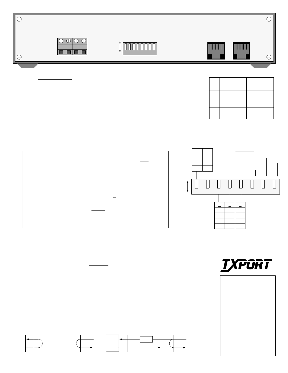
TxPORT 210 Rear Panel
TxPORT Customer Service
127 Jetplex Circle
Madison, Alabama 35758
Customer Service Returns:
800-926-0085, ext. 227
Product Technical Support
(8 a.m. to 5 p.m.)
800-285-2755 or
205-772-3770, ext. 255
After Hours Hot Line:
205- 551-7538
DTE
NET
Local Loopback
DTE
NET
Remote Loopback
AIS
8
1
NET
8
1
DTE
8
6
5
4
3
2
1
7
S1
PWR
(+) GND
PWR
(-) GND
-20 to -56 VDC
MAX CURRENT, 100 MA
A
B
Pin
NET
DTE
1
Data In (R1)
Data Out (R)
2
Data In (T1)
Data Out (T)
3/ 6
Not Used
Not Used
4
Data Out (R)
Data In (R1)
5
Data Out (T)
Data In (T1)
7/ 8
Chassis Gnd
Chassis Gnd
RJ48C Interfaces
210 CSU connections are made on
the following terminals using 20-
gauge stranded (or similar) wire:
GND (Ground)
PWR- (- 48 VDC, ± 6 V, 45 mA)
PWR+ (Return)
Power Connection
A
Loo
p
5
4
3
2
1
6
8
B
Lo
op
AIS
Ne
tw
o
rk Da
ta
7
One
s De
nsit
y
15 Z
ero
s
One
s De
nsit
y
17
5 Z
e
ros
B
B
B
A
A
A
B
A
0
-22.5
-7.5
-15
Network
LBO
B
A
A
B
A
B
A
B
A
A
B
A
B
B
B
DTE
LBO
134 - 266 FT.
0 - 133 FT.
267 - 399 FT.
400 - 533 FT.
534 - 655 FT.
Switch S1
1-2 Network LBO: These 2 positions set the network line build out signal level of data
transmitted towards the T1 facility. The output level is factory set at 0 dB. It may be
attenuated by -7.5 dB, -15 dB, or -22.5 dB if operating conditions require a change.
Refer to the diagram of Switch S1 for settings.
3-5 DTE LBO: These 3 positions set the DTE line build out transmit signal value
towards the customer equipment. Refer to the diagram of Switch S1 for settings.
6
AIS Enable: Options the unit to either ‘generate’ unframed all ones (an Alarm
Indication Signal) to the DTE during a remote loop (A) or to ‘pass’ the received net-
work signal to the DTE on a remote loop (B).
8
Ones Density: Per AT&T 62411, the ‘Enabled’ mode allows ones density insertion
after 15 successive zeros from the DTE. The ‘Disabled’ mode ignores density con-
trol and allows up to 175 zeros to pass towards the network before a loss of signal is
declared.
NOTE: The ‘A’ position is the factory default for
all switch settings. If a particular user configura-
tion requires that a switch be placed in the ‘B’
direction, then mark this sheet for future reference.
Loopbacks
The unit can be looped remotely by generating towards it a standard CSU line loopback code (00001
repeating for Š 5 seconds, framed or unframed). Once looped, the received signal from the T1 facility
(NET IN) is regenerated and transmitted back to the T1 facility (NET OUT). The unit is unlooped
remotely by generating towards it a standard CSU line unloop code (001 repeating for Š 5 seconds,
framed or unframed).
DIP switch S1-6 configures the unit to either generate an unframed all ones (AIS) signal to the DTE or
to pass the received data from the network to the DTE.
L
in
e Co
de
T
ran
sp
ar
en
t
DTE
AMI to
NET B
8
Z
S
Switch S1 Description