Watson-Marlow MR-Series User Manual
Page 20
Revision 1.4 / August 2013
Visit our website at
www.masosine.com
20
Scrapergate and Scrapergate Guide Installation Instructions
When inserting the scrapergate into the scrapergate guide, the markings on the ends of both parts
must match. This ensures that the wider side of the scrapergate will contact the wider section of the
scrapergate guide.
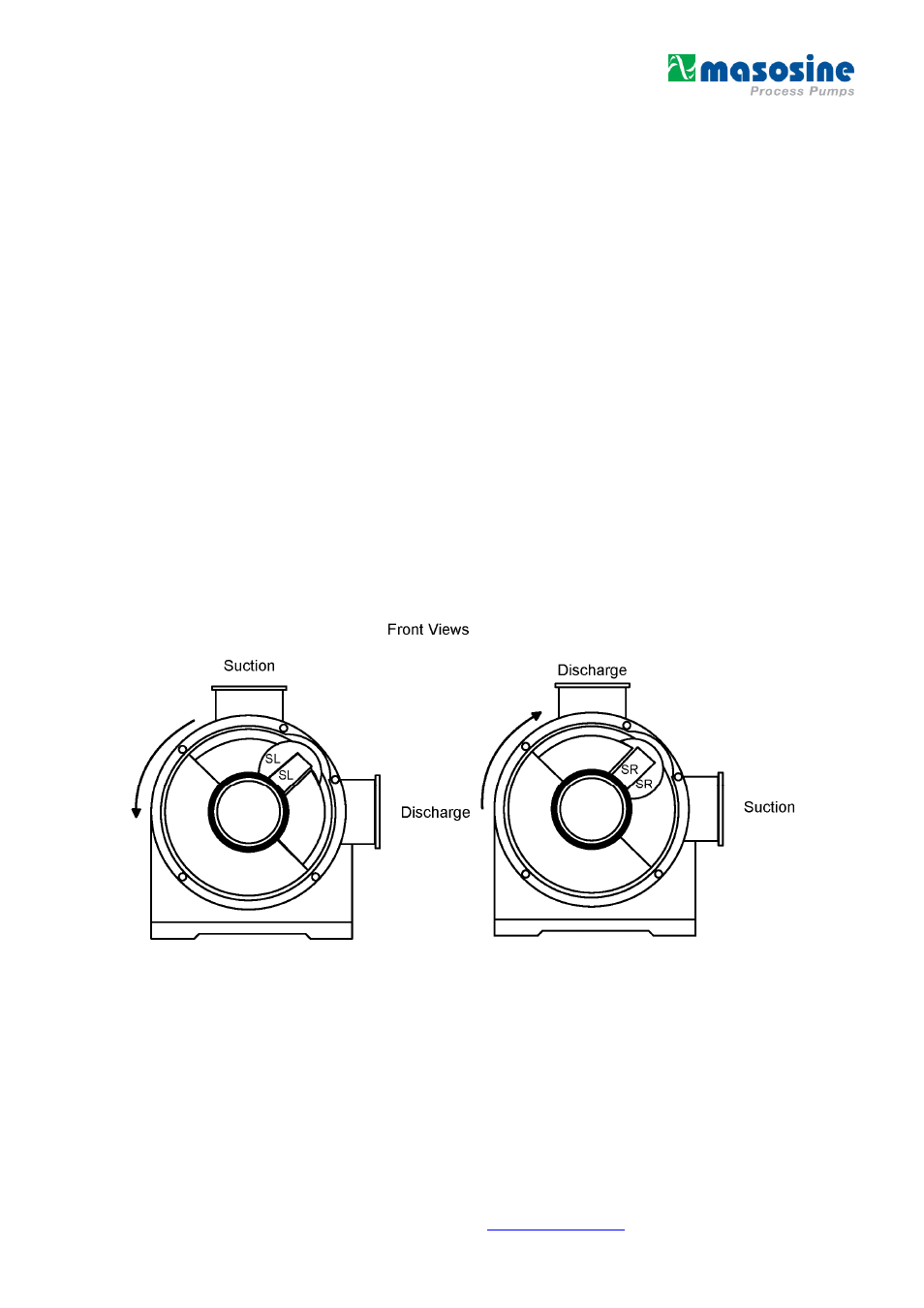
Your suction conditions coupled with the nozzle orientation determine how the scrapergate and
scrapergate guide should be installed in the MasoSine Pump. The two most common MasoSine Pump
flow conditions are shown in
Figure 10
. When viewing the pump from the front (where the front cover is
located), if the product were to enter the MasoSine Pump through the nozzle located at the 12 o'clock
position and leave the pump through the nozzle located at the 3 o'clock position as depicted on the left
in
Figure 10
the suction left condition would apply. Thus, the scrapergate and scrapergate guide should
be installed with the "SL" markings facing out towards the front cover of the pump. This corresponds to
a counterclockwise rotation of the shaft.
When viewing the pump from the front, if the product were to enter the MasoSine Pump through the
nozzle located at the 3 o'clock position and leave the pump through the nozzle located at the 12
o'clock position as depicted on the right in
Figure 10
, the suction right condition would apply. Thus the
scrapergate and scrapergate guide should be installed with the "SR" markings facing out towards the
front cover of the pump. This corresponds to a clockwise rotation of the shaft.
To change the orientation of the scrapergate and scrapergate guide, follow steps 1 through 6 of the
Wet End Disassembly section of this manual. Rotate the scrapergate and scrapergate guide and then
follow steps 7 throughl 3 of the Wet End Assembly section of this manual.
Figure 10 – Scrapergate (Guide) Installation Instructions