Technical guide systems 12, Controls – WattMaster VAV Systems User Manual
Page 12
Technical Guide
Systems
12
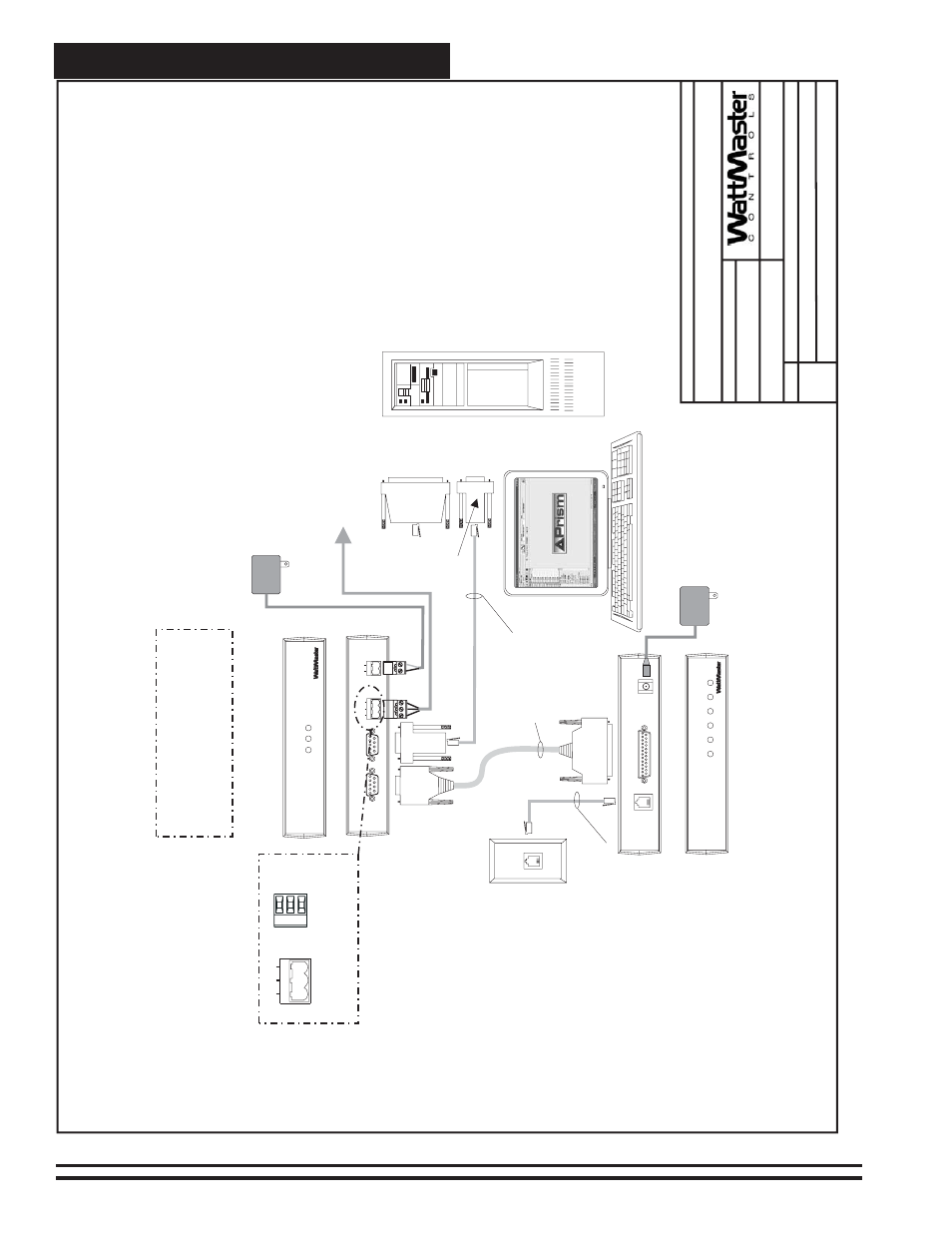
Figure 5: Typical Networked Multiple Loop System - Connections & Wiring Using Computer & Remote Link
03/24/04
V
A
V
-Network-MultLoop1B.CDR
FILENAME
DA
TE:
B.
Crews
DESCRIPTION:
P
AGE
DRA
WN
BY
:
Wiring
&
Connection
Diagram
JOB
NAME
2o
f3
Network
System
-
Multiple
Loop
9
Pin
Female
End
T
elephone
Cable
Assembly
9
Pin
Female
Connector
9
Pin
Female
Connector
Molded
Cable
Assembly
25
Pin
Male
End
25
Pin
Female
Connector
(If
Reqd)
Connect
T
o
Computer
Serial
Port
Personal
Computer
(By
Others)
Dedicated
T
elephone
Outlet
(By
Others)
Back
V
iew
of
CommLink
Back
V
iew
of
Remote
Link
Front
V
iew
of
CommLink
Note:
If
Direct
Computer
Connection
Is
Required,
Connect
T
o
PC
As
Shown.
Remote
Link
Is
Only
Required
If
Alarm
Callout
Or
Remote
Computer
Connection
Is
Required.
Front
V
iew
of
Remote
Link
CL
II
omm
ink
LOOP
24V
T
G
R
GND
REMOTE
LINK
(DTE)
COMPUTER
(DCE)
485LOO
P
ST
A
TUS
POWER
COMP
RLINK
SERIAL
#
CONTROLS
RL
emote
ink
SIG
TELCO
LINE
TELCO
LINE
SERIAL
D
A
T
A
DET
RDY
SND
REC
PWR
SERIAL
#
CONTROLS
8
Conductor
Modular
Cable
Assembly
11
0
V
A
C
T
o
9
VDC
Power
Pack
11
0
V
A
C
T
o
24
V
A
C
Power
Pack
CommLink
Remote
Link
(Optional)
Connect
T
o
MiniLink
PD
Network
T
erminals
See
Page
1
O
f
This
Drawing
POWER
9VDC
@
500mA
SHLD
T
R
T
ypical
T
erminal
Blocks.
All
W
iring
T
o
Be
T
T
o
T
,
SHLD
(G)
T
o
SHLD
(G
)&RT
oR
T
G
R
485LOOP
Optional
Computer
Connection
Dia
g
ram
Using
R
e
mote
Link
F
o
r
R
emote
Connection