2 connections – Westermo FD-80 User Manual
Page 8
8
6630-2281
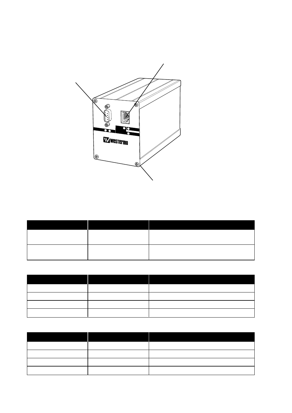
6.2 Connections
Profibus DP interface
9-pol D-sub, female
Ethernet/Service interface,
10Base-T, RJ-45 8-pin Modular Jack
Power interface
24 V DC
6.2.1 Power interface
6.2.2 Profibus DP interface
6.2.3 Ethernet/Service interface
Connection
Description
Note
Red conductor (+)
+24 V DC
From the units 2-pos screwblock
nearest the DIN-rail support
Black conductor (–)
0 V DC
From the units 2-pos screwblock
nearest the front
Connection
Direction
Description
9-pos D-sub no. 3
In/Out
Receive/Transmit-Data-P (RxD/TxD-P)
9-pos D-sub no. 5
–
DGND
9-pos D-sub no. 6
–
+5V
9-pos D-sub no. 8
In/Out
Receive/Transmit-Data-N (RxD/TxD-N)
Connection
Direction
Description
RJ-45 no. 1
Out
Transmit data (TD+)
RJ-45 no. 2
Out
Transmit data (TD–)
RJ-45 no. 3
In
Receive data (RD+)
RJ-45 no. 6
In
Receive data (RD–)
DIAG
ER-E
BA
POWER
STATUS
FD-80
FIELDBUS ADAPTER
PROFIBUS D
P SLAVE - TC
P/IP