1 power interface, 4 antenna interface, 5 sim card interface – Westermo GD-01 US User Manual
Page 15
Advertising
15
6696-2230
Connection
Direction
Description
No. 1Out
DCD
No. 2
Out
RD
No. 3
In
TD
No. 4
In
DTR
No. 5
-
Signal ground
No. 6
Out
DSR
No. 7
In
RTS
No. 8
Out
CTS
No. 9
Out
RI
Connection in GD-01 US
Direction
Description
5-pos screw terminal
No. 1–
Signal ground
No. 2
Out
CTS
No. 3
In
RTS
No. 4
Out
RD
No. 5
In
TD
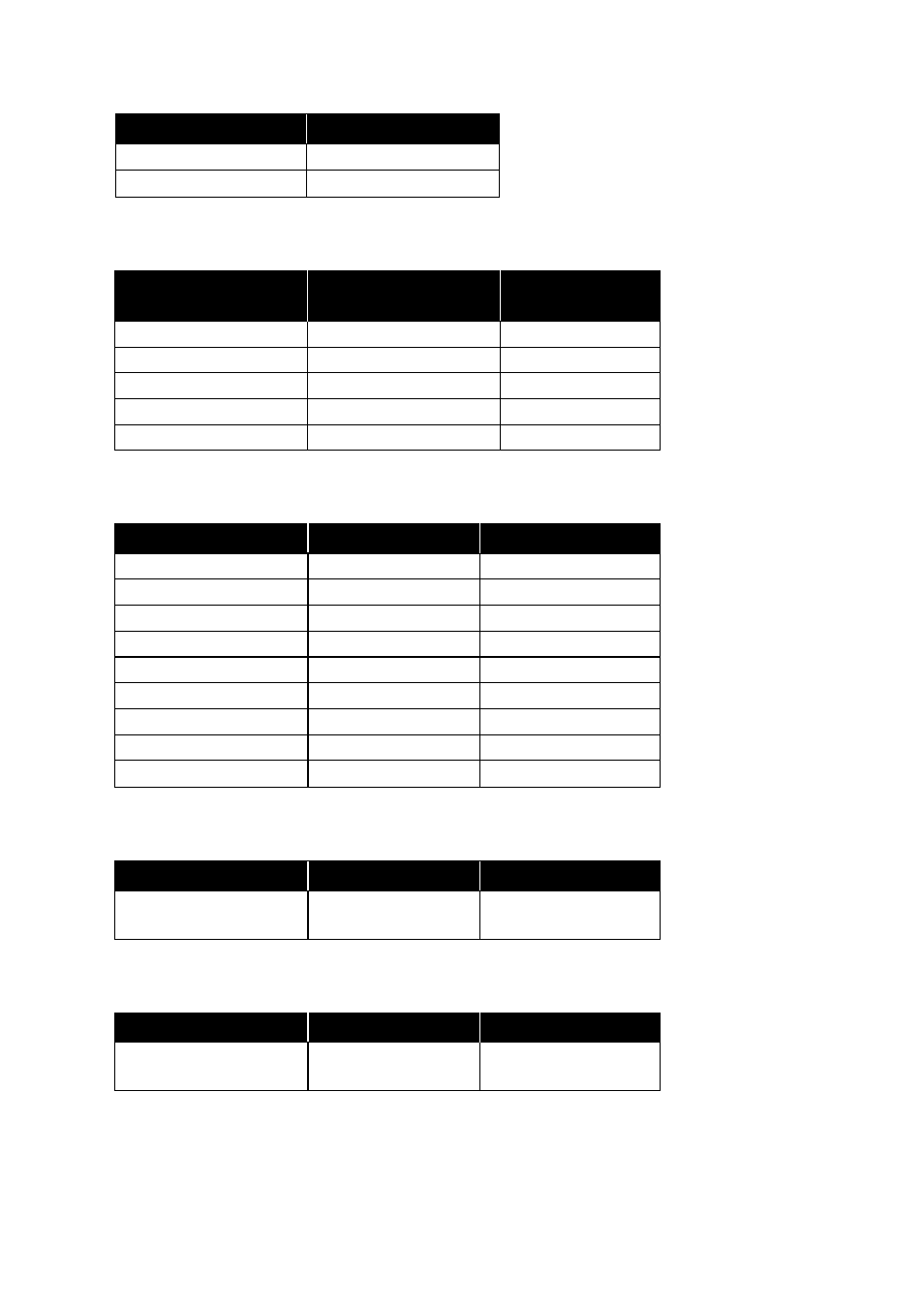
7.4.1 Power interface
2-pos screw terminal
Description
No. 1–VDC
No. 2
+VDC
7.4.2 RS-232 interface, screw terminal
7.4.3 RS-232 interface, 9-pin D-sub
Connection
Direction
Description
SMA female connector
–
2W @ GSM 850
1W @ GSM 1900
7.4.4 Antenna interface
Connection
Direction
Description
SIM card
–
Supported SIM card
voltage: 3 volt
7.4.5 SIM card interface
Advertising