V or y function factory settings, S1:3 and 4 not used see functional description – Westermo LD-01 User Manual
Page 3
Advertising
9
6154-2001
12
3
4
56
7
8
9
S1:1-4
J1
J2
1 2 3
1 2 3
1 2 3 4 5
LD-01 DC
-
+
TD
RD
DCD 4
12-36V
DC
R+ R- T+ T-
PWR
V24/RS-232-C
CONNECTION
CHANNEL 1
POWER
DCD 3
DCD 2
CHANNEL 3
CHANNEL 4
9
8
7
6
5
4
3
2
1
R+ R- T+
T-
T+ T-
R+ R-
CHANNEL 2
WARNING!
DO NOT OPEN CONNECTED UNIT
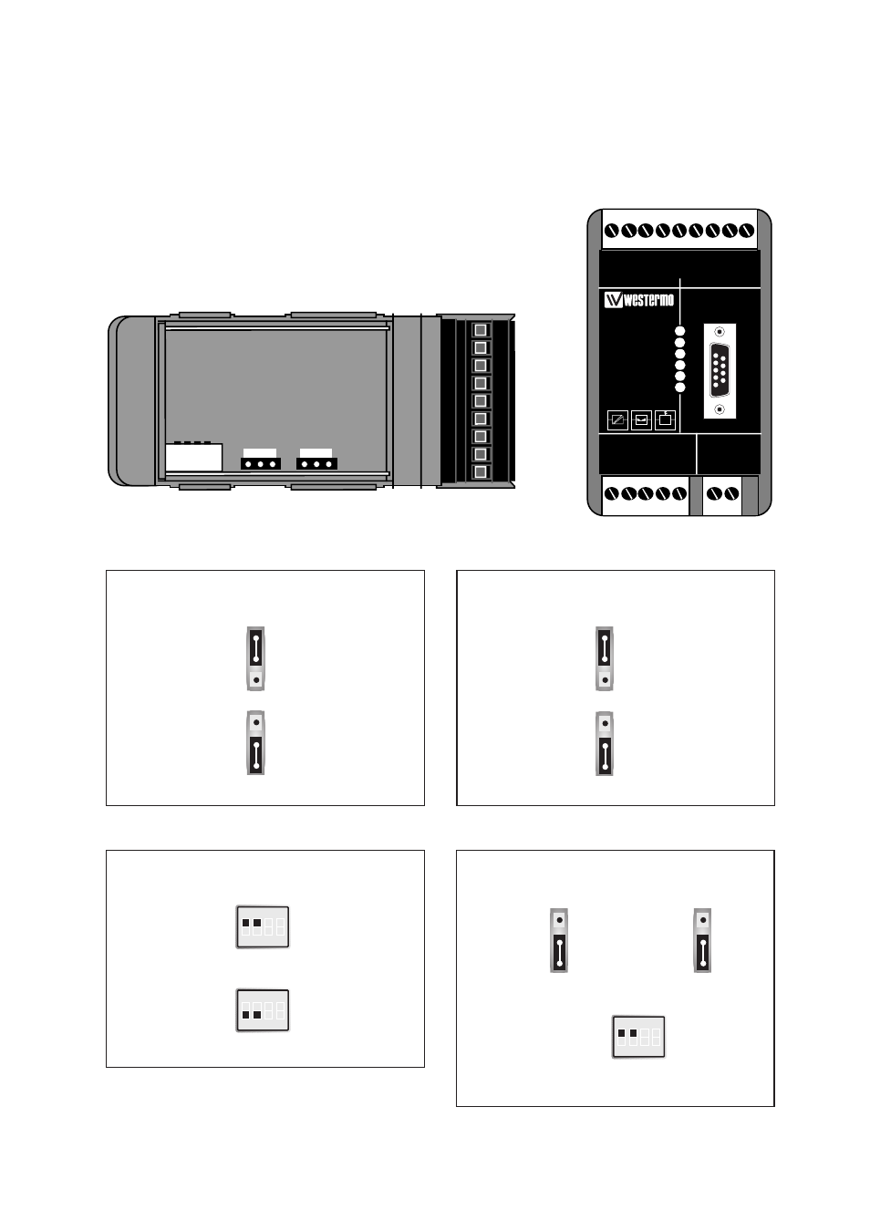
Switch settings
The LD-01 can through different switch settings be adapted to a variety of running
conditions. To set the switches, open the lid on the top of the plastic case.
V or Y function
Factory settings
Y
S1
ON
1 2 3 4
V
S1
ON
1 2 3 4
RS-232-C/V.24 or W1, Channel 2
RS-232-C/V.24
S1
ON
1 2 3 4
J1
W1
J1
RS-232-C/V.24 or W1, Channel 3
S1:3 and 4 not used
See functional description
3
2
1
3
2
1
3
2
1
RS-232-C/V.24
J2
W1
J2
3
2
1
J1
3
2
1
J2
3
2
1
Advertising