Connections – Westermo LD-01 User Manual
Page 4
10
6154-2001
Direction
RS-232-C/V.24
CCITT V.24
Description
DCE
Channel 1 Channel 2 Channel 3
Circuit no.
O
1
109
DCD/Data Carier Detect
O
2
4
6
104
RD/Received Data
I
3
2
8
103
TD/Transmitted Data
I
4
108/2
DTR/Data Terminal Ready
–
5
5
5
102
SG/Signal Ground
O
6
107
DSR/Data Set Ready
I
7
105
RTS/Request To Send
O
8
106
CTS/Clear To Send
NC
9
Connections
Connection RS-232-C/V.24
Direction
Pin configuration 10mA balanced current loop
Signal name
Channel 2
Channel 3
Channel 4
Receiver
1
9
2
R+
Receiver
2
8
1
R-
Transmitter
3
7
4
T+
Transmitter
4
6
3
T-
5
5
5
1) Shield
Line connection
1) If shielded cable is used, connect the shield only at one end to avoid ground currents.
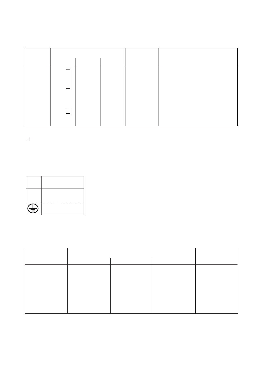
N
115V*/230V
L
AC power
PE/Protective Earth
Power connection (AC)
(3-position screw-terminal)
* LD-01 115V only
Screw
no.
Power
Supply
I = Input O = Output, the LD-01 is a DCE (Data Communication Equipment) NC = Not connected
= the signals are only connected with each other.