Wiring the relay output, Connecting to network, Dip switch settings for alarm relay output – Westermo SDI-5xx User Manual
Page 3
NO
12
5
4
3
P1 to P5
(Pin1 ~5)
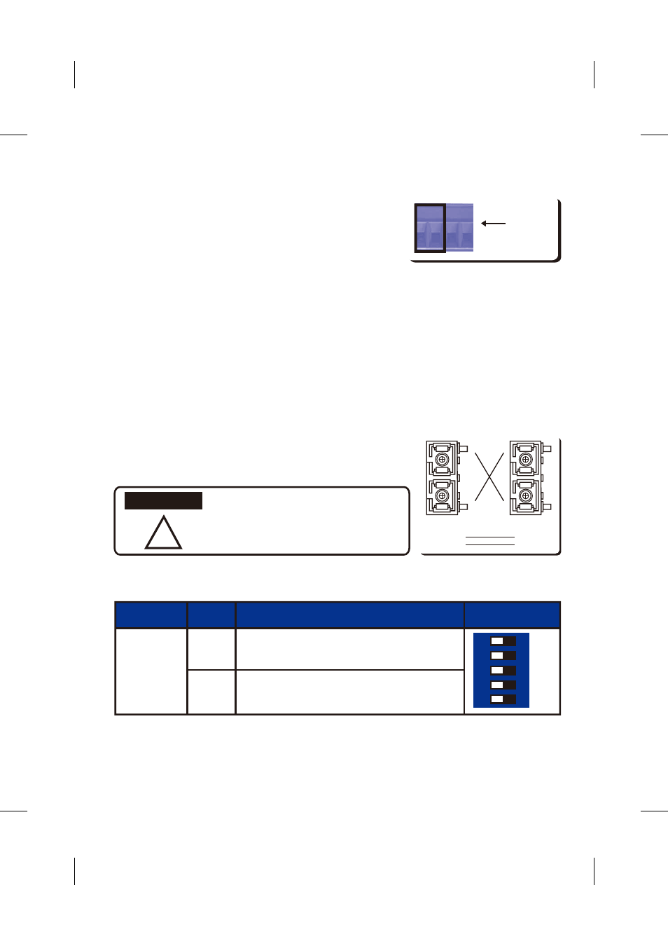
Pin No. #
Status
Description
ON
Off
To enable port break alarm at this port.
To disable port break alarm at this port.
Alarm Switch
Ȋ
This is a Class 1 Laser/LED product.
Don’t stare into the Laser/LED Beam.
ATTENTION
RX
RX
TX
TX
Cable Wiring(SC to SC)
RX A TX B
TX A RX B
Wiring the Relay Output
The relay output alarm contacts are in the middle of the
terminal block connector as shown in the figure.
By inserting the wires and set the DIP switch to "ON", relay
output alarm will detect any port failures, and form a short
circuit. The alarm relay output is "Normal Open".
Connecting to Network
1. Connecting the Ethernet Ports: Connect one end of an Ethernet cable into the UTP port of
SDI-550/541, while the other end is connected to the attached networking device. All UTP ports
support auto MDI/MDIX function. The LNK / ACT LED will turn Yellow for 10M Ethernet or Green
for 100M Ethernet.
2. Connecting the Fiber Port (SDI-541) : Connect the fiber port on your SDI-541
to another Fiber Ethernet device, by following the figure below.
Wrong connection will cause the fiber port not working properly.
DIP Switch Settings for Alarm Relay Output
Alarm
V-
V+
Relay Output,
Carry ability 1A @24V