Functional description, Wire – Westermo TD-29P User Manual
Page 13
Advertising
GB.27
6611-2022
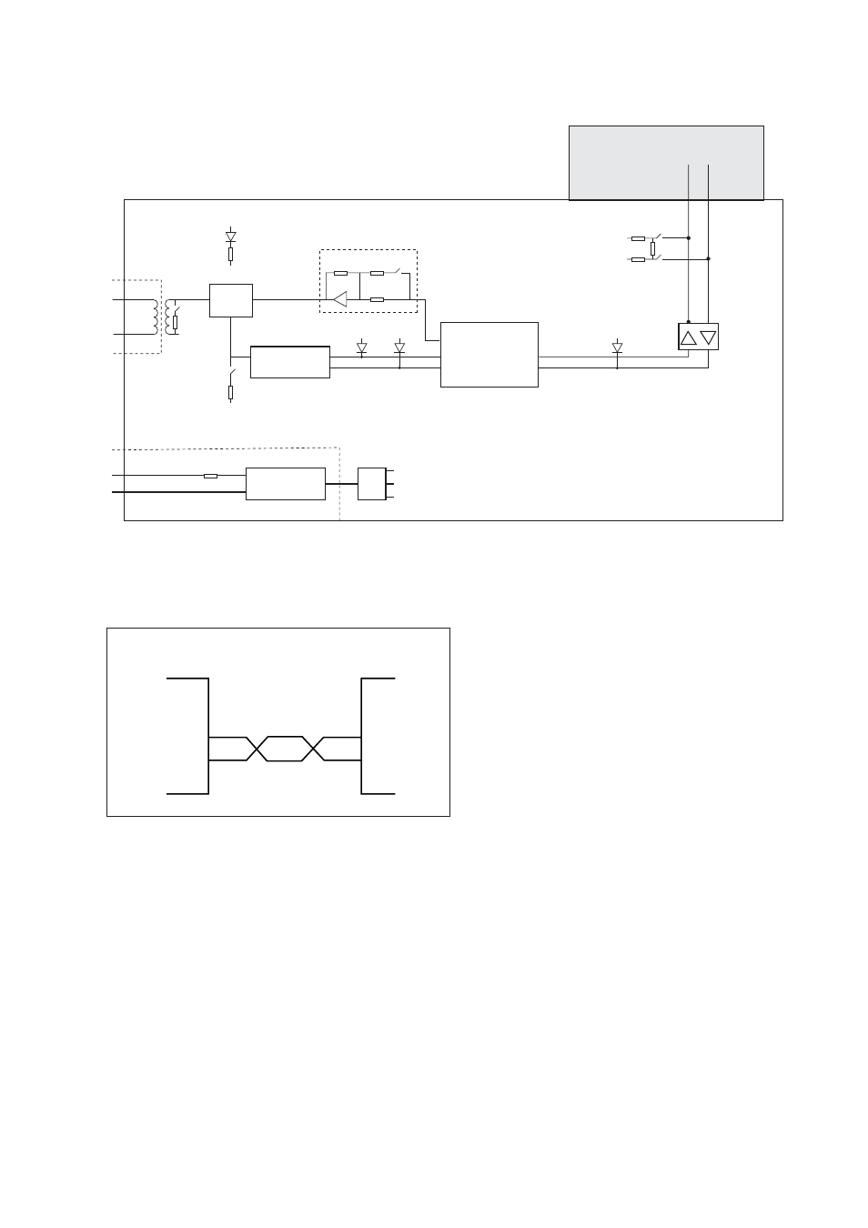
7. Functional description
7.1 Block diagram
7.2 RS-485 connection
Amplifier S1:6
S1:7
RD
LED
DCD
LED
B
A
Screw terminal
1
2
3
4
5
6
7
8
0V
F1
0V
+5V
–5V
0V
S2:4
S2:3
5V
0V
9
TD
LED
MCU
1–5, 7–9 not used
FSK
Demodulator
Isolated
Power Supply
S1:4
0V
0V
PWR
LED
Line
switch
Line
Power Supply
2-wire
7
6
A/A’
B/B’
B/B’
A/A’
Twisted pair
TD-29P
RS-485
equipment
Transmitter/
Receiver
Transmitter/
Receiver
Advertising
See also other documents in the category Westermo Equipment:
- TR-36B (88 pages)
- TD-36 (44 pages)
- TR-36 (36 pages)
- TR-36B (20 pages)
- IDW-90 AT (97 pages)
- GD-01 (206 pages)
- GD-01 (20 pages)
- MRI-128-F4G (175 pages)
- MRI-128-F4G (169 pages)
- GDW-11 (40 pages)
- GDW-11 485 (380 pages)
- Lynx Series (28 pages)
- ODW-720-F2 (36 pages)
- ODW-720-F1 (20 pages)
- ODW-720-F1 (24 pages)
- ODW-730-F2 (36 pages)
- ODW-730-F1 (24 pages)
- DDW-120 (24 pages)
- DDW-226-EX (24 pages)
- DDW-226-EX (24 pages)
- DR-270 (28 pages)
- DR Series (460 pages)
- ED-2x0 (20 pages)
- MRD-3x0 (199 pages)
- FD-80 (24 pages)
- FDV-206-1D-1S (24 pages)
- GD-01 US (24 pages)
- LD-01 (8 pages)
- IDW-90 (44 pages)
- Lynx-x10-F2G (16 pages)
- Lynx-x08-F2G-S2 (20 pages)
- MDI-110-F3x (16 pages)
- MR-2x0 (28 pages)
- ODW-642 (28 pages)
- PII PoE Injector (12 pages)
- Viper Series (977 pages)
- SDI-5xx (12 pages)
- RFI-xx (32 pages)
- SDI-8xx (16 pages)
- RFIR-xxx (24 pages)
- TD-29 (16 pages)
- SDW-5xx (24 pages)
- TD-23 (24 pages)
- Viper 408 (20 pages)