Led indicators – Westermo DR-250 User Manual
Page 12
12
6622-2211
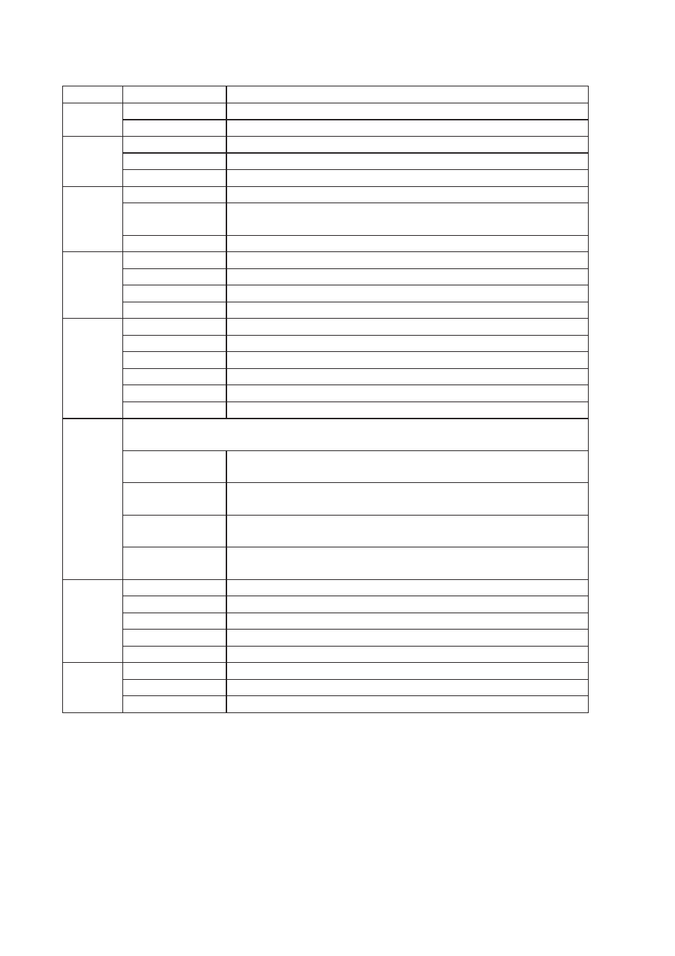
LED Indicators
LED
Status
Description
PWR
ON
In service
OFF
Out of service
LAN
0, 1, 2, 3
ON
Network connection on LAN port
OFF
No connection on LAN port
Flash
Transmit or recive data on LAN port
DTE
ON
Terminal connected to the serial port and the DTR signal is on
OFF
No connection on serial port Data is transmitted or received on
the serial port
Flash
Data is transmitted or received on the serial port
DSL
ON RED
No DSL is detected
FLASH RED
DSL training
ON GREEN
DSL active
FLASH GREEN
Data being transferred
W-WAN
NET ON
A wireless network has been detected
OFF
No wireless network has been detected
SIM ON
A valid SIM card is installed in the unit
OFF
No valid SIM card is installed in the unit
DAT Flash
Data is being transferred over the wireless network
OFF
No data is being transferred over the wireless network
Signal
The three indicators labelled SIGNAL illuminate to indicate the GSM signal strength
as follows:
None
illuminated
< -113 dBm (effectively no signal)
1 LED
illuminated
>= -112 dBm and <= –87 dBm (weak)
2 LED’s
illuminated
>= -86 dBm and <= –71 dBm (medium)
3 LED’s
illuminated
>= -70 dBm and <= –51 dBm (strong)
ISDN
D ON
Connected to ISDN network and D-channel active
B1 ON
ISDN B-channel 1 active
FLASH
Data being transferred
2 ON
ISDN B-channel 2 active
FLASH
Data being transferred
PSTN
OH ON
Modem off-hook
CD ON
Connected to a remote modem
DAT FLASH
Data being transfered
Reset switch
This is located on the underside of the unit near the front. Pressing the switch gently with the tip of
a pen or other suitable implement will generate a hardware reset.
Refer to page 15 (restoring factory defaults)
It is important to allow the DR-250 to complete the restore procedure. DO NOT press the reset
button again or power cycle the unit for at least 2 minutes.