Installation – Westermo DR-250 User Manual
Page 13
13
6622-2211
Installation
Mounting / Removal
The router should be positioned on a smooth, level surface making sure that there is
adequate ventilation. Do not expose the router to extremes of heat or cold, strong
magnetic fields or liquids.
If the GSM option is fitted it is important to remember that these products are wireless
devices just like a mobile phone, so they will only operate reliably over the GSM network
if there is a good signal.
For many applications the stub aerial provided will be suitable but in some circumstances
it may be necessary to use a window-mounted or magnetically mounted aerial with an
extended cable to allow the aerial itself to be positioned to provide the best possible
signal reception. Westermo can supply a range of suitable aerials.
Step 1 – Installing the SIM card(s) (wireless option)
The router incorporates two separate SIM card holders so that if your application
demands it, you may install SIM cards for two different networks. This means that one
wireless service may be used as a back-up service in the event that the primary service
fails in some way. By default, SIM 1 is the default SIM used for access to the primary
network and SIM 2 is used for the back-up network.
Note: SIM 1 and SIM 2 cannot be used to access two networks simultaneously.
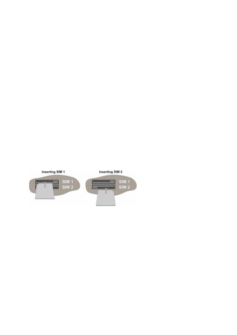
The SIM card(s) should be inserted into SIM cardholders on the right of the front panel
as illustrated below.
In both cases, the end of the SIM card with the chamfered corner should be inserted first.
For SIM 1 the contacts should be face down. For SIM 2 the contacts should be face up.
The easiest way to get started is to use SIM-cards without PIN-code. If the PIN-code is
activated it is possible to set this up in the settings for the router.
Step 2 – Fitting the wireless antenna (if applicable)
The router is supplied with a “stub” antenna suitable for with the model you have
ordered. Alternatively you may have ordered a different type of antenna separately. In
either case this should be screwed onto the SMA aerial connector on the rear of the
unit.
Step 3 – Connecting the LAN cable
Plug one end of one of the supplied 2 metre CAT5 STP cable into the RJ45 socket
labelled LAN 0. Plug the other end into the LAN socket on your PC or notebook.