Location of interface ports and led’s, Ethernet connection tx (4 ports) – Westermo Lynx-x05-S1 User Manual
Page 11
11
6643-2230
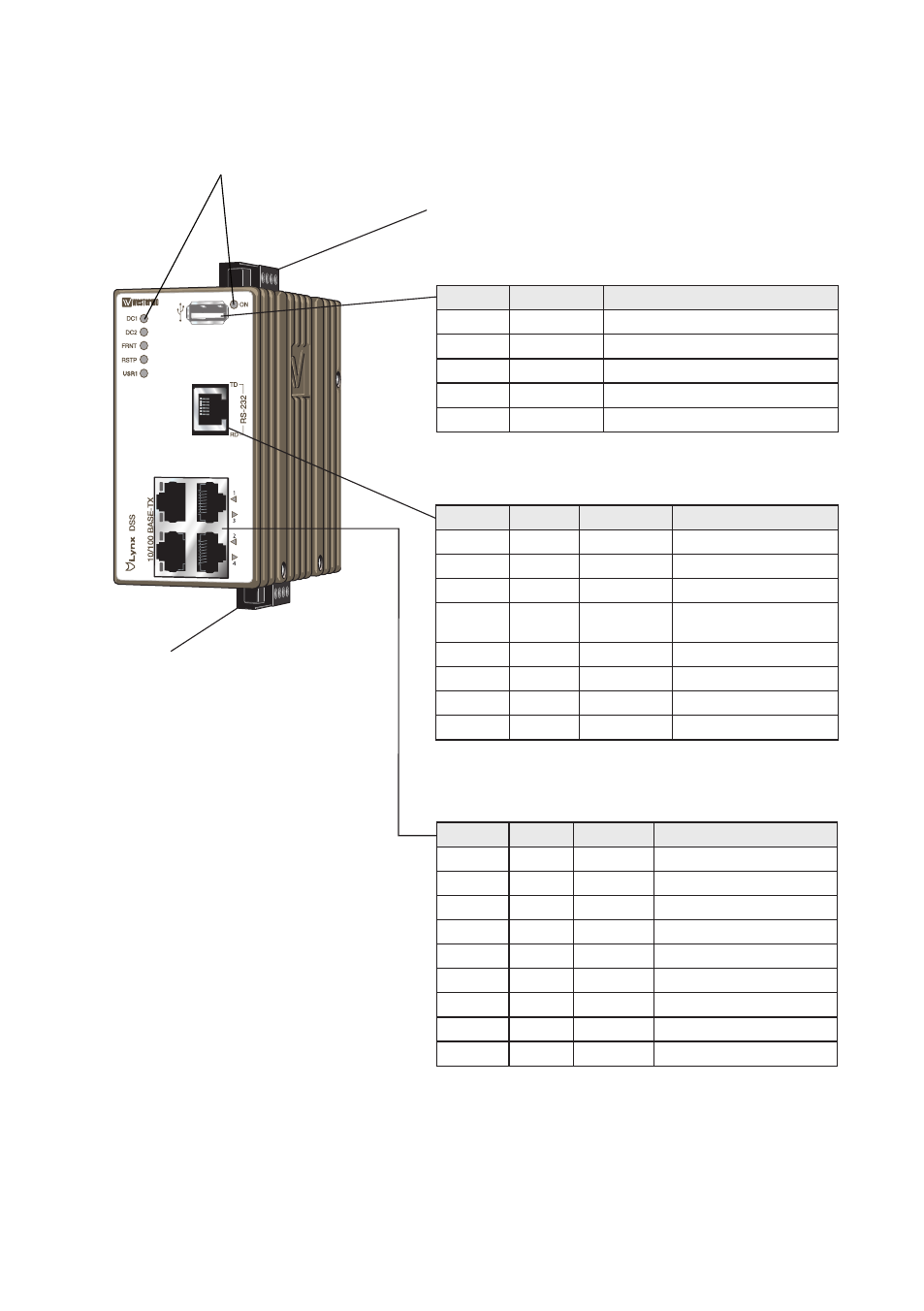
Location of interface ports and LED’s
LED Indicators (for details see page 14)
Power connection (for details see page 9 and 13)
I/O connection
(for details see page 10 and 13)
USB
Position
Direction
Description
No. 1
Out
VBUS
No. 2
In/Out
D–
No. 3
In/Out
D+
No. 4
Out
GND
Shield
In/Out
Connected to protective earth
RS-232
Position
Signal
Direction
Description
No. 1
DSR
Out
Data Set Ready
No. 2
DCD
Out
Data Carrier Detect
No. 3
DTR
In
Data Terminal Ready
No. 4
SG
–
Signal Ground, not chas-
sis ground
No. 5
RD
Out
Receive Data
No. 6
TD
In
Transmit Data
No. 7
CTS
Out
Clear To Send
No. 8
RTS
In
Request To Send
Ethernet connection TX (4 ports)
Position
Signal Direction Description
No.1
TD+
In/Out
Transmitted/Received data
No. 2
TD–
In/Out
Transmitted/Received data
No. 3
RD+
In/Out
Transmitted/Received data
No. 4
–
Not Connected
No. 5
–
Not Connected
No. 6
RD–
In/Out
Transmitted/Received data
No. 7
–
Not Connected
No. 8
–
Not Connected
Shield
Connected to PE