Danger! do not open connected unit, Switch settings, Switch settings ma-12 – Westermo MA-12 User Manual
Page 3: Transmitter (carrier) activated by, Cts controlled by, Factory settings
9
6012-2001
Danger! Do not open connected unit
1 2 3 4 5
LINE
CONNECTION
V.24/RS-232-C
CONNECTION
Switch settings
Transmitter (carrier) activated by
ON
1 2 3 4 5 6 7 8 9
S1
Always active
ON
1 2 3 4 5 6 7 8 9
S1
AUX
ON
1 2 3 4 5 6 7 8 9
S1
SRS
ON
1 2 3 4 5 6 7 8 9
S1
RFR
ON
1 2 3 4 5 6 7 8 9
S1
RTS
ON
1 2 3 4 5 6 7 8 9
S1
DTR
ON
1 2 3 4 5 6 7 8 9
S1
DTR and AUX
ON
1 2 3 4 5 6 7 8 9
S1
DTR and SRS
ON
1 2 3 4 5 6 7 8 9
S1
DTR and RFR
ON
1 2 3 4 5 6 7 8 9
S1
DTR and RTS
CTS controlled by
ON
1 2 3 4 5 6 7 8 9
S1
RTS
ON
1 2 3 4 5 6 7 8 9
S1
Always high
ON
1 2 3 4 5 6 7 8 9
S1
DCD
ON
1 2 3 4 5 6 7 8 9
S1
Factory settings
ON
1 2 3 4 5 6 7 8 9
S2
S1
ON
OFF
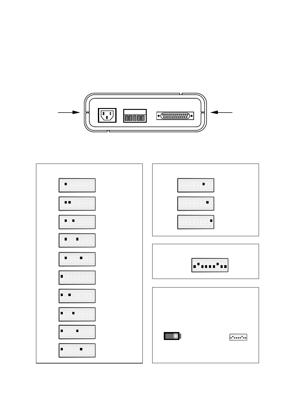
S1 Selection of signal activating transmitter (carrier)
Selection of signal controlling CTS
S2 Selection of power supply 115/230V AC
Switch settings MA-12
The MA-12 can through different switch settings be adapted to a variety of running con-
ditions. To set the switches, open the plastic case by placing and turning a screw-driver
between top and bottom at the rear of the case.