Connections, Line connection, Transmission range (interface 2) – Westermo MA-21 User Manual
Page 4
10
6021-2002
Cable
42pF/m
0.3mm
2
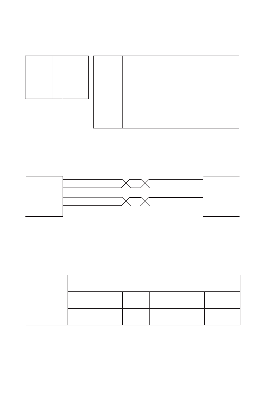
1200
5000m
600
6000m
2400
4000m
4800
3000m
9600
500m
19200
200m
I
2
103
TD/Transmitted Data
O
3
104
RD/Received Data
I
4
105
RTS/Request To Send
O
5
106
CTS/Clear To Send
O
6
107
DSR/Data Set Ready
–
7
102
SG/Signal Ground
O
8
109
DCD/Data Carrier Detect
I
11
–
AUX/Auxiliary
I
19
120
SRS/Secondary Request to Send
I
20
108/2
DTR/Data Terminal Ready
Receiver
1
R+
Receiver
2
R-
Transmitter 3
T+
Transmitter 4
T-
5
Shield
No.
1) I= Input O= Output on MA-21
Direction
Description
Description
Direction 1)
Pin
no.
CCITT V.24
Circuit no.
Connections
Line connection
(5-position screw-terminal)
Terminal connection (DCE)
(RS-232-C/V.24, 25-position D-sub, female)
5
Line connection
Transmitter
Receiver
Receiver
Transmitter
Shield 1)
4
3
2
1
R+
R-
T+
T-
T+
T-
R+
R-
MA-21
Twisted pairs
20mA current loop
equipment
1) If shielded cable is used, connect the shield only at one end to avoid ground currents.
Transmission range (interface 2)
Transmission rate bit/s