Hints – Westermo MA-49 User Manual
Page 6
12
6049-2001
Hints
The MA-49 uses the RS-422/485 interface.
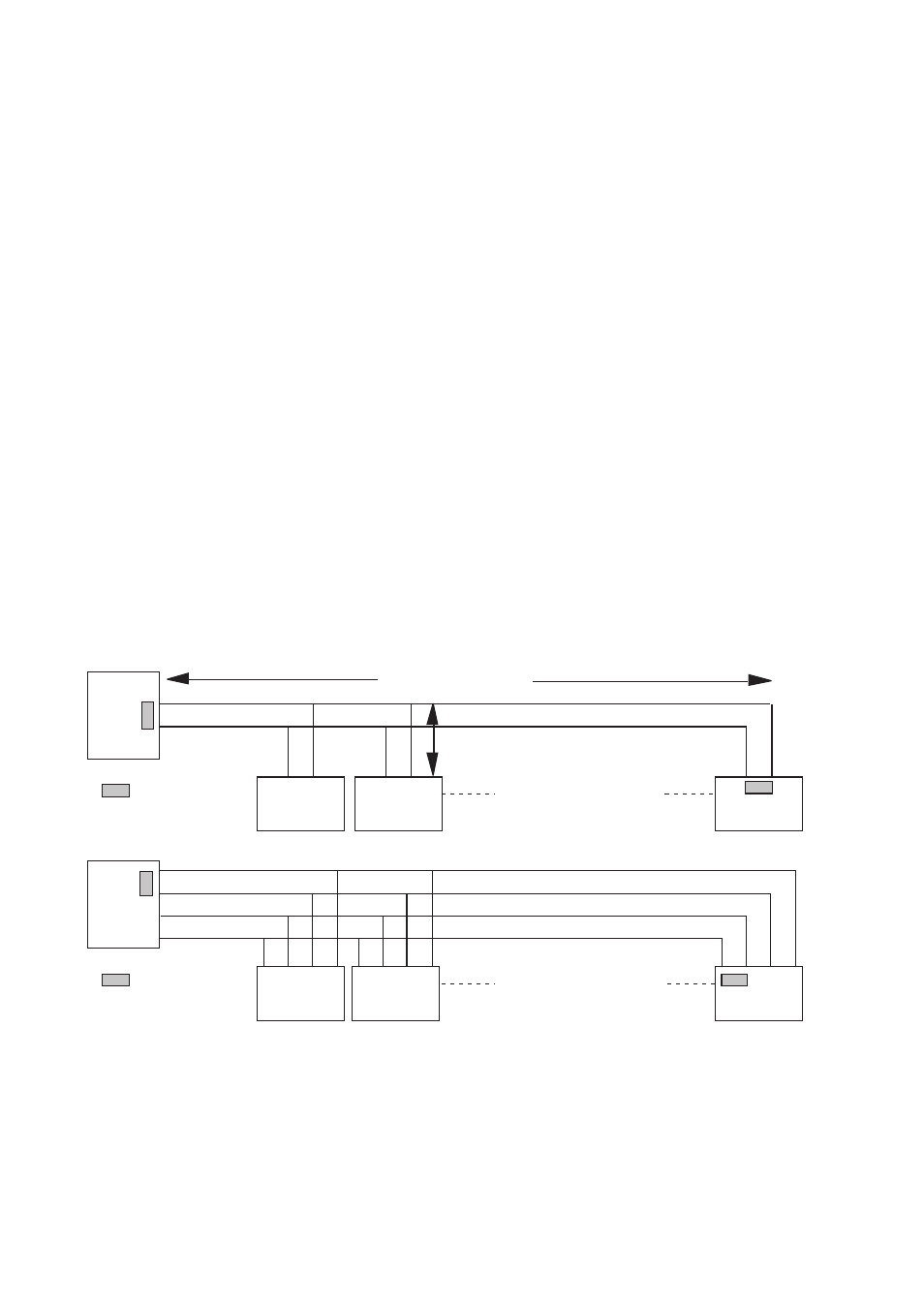
RS-422/485 was designed for multidrop applications. When a system is installed it
should form a bus structure (see diagrams). Star shaped networks should never be
created, there are other Westermo products designed to work in star net applications.
To correctly install, an RS-422/485 network should be terminated at the correct points.
The recommendation is to terminate the receivers at both end of network.
See diagrams for details of how this is done with RS-485 (2 wire) and RS-422 (4 wire).
On 4 wire systems when the MA-49 is on a slave system, it’s transmitter is linked to
the same bus as all the other slave transmitters. A status signal (RTS or DTR) is used to
control the MA-49’s transmitter, to ensure only one slave is active on the bus at one
time. The status signal is also used to control direction for RS-485 (2 wire) transmission.
If any problems do occur on set up of the MA-49, the LED’s will be helpful.
• RTS:Indicates that the RS-422/485 transmitter is activated.
• CTS: Follows RTS.
• DCD:Simulated carrier due to the setting of S2.
• RD:Data received on the RS-422/485 interface.
• TD:Data received on the RS-232 interface.
• +12V, –12V:Indicates positive and negative power supply respectivly.
=Termination
Max 32 connections
Max 1 200 metres
Max 0.3 metre
=Termination
Max 32 connections
A
B
A
B
A
B
A
B
A’
B’
A
B
B’ A’
A’
B
B
A
B’ A’ B A
A
B’
N.B. R+/R–, T+/T– definitations are not standard, it can help to shift A and B
if the unit not will work.