Typical attenuation in connectors, Typical attenuation in splice, Power budget – Westermo MA-67 User Manual
Page 5: Attenuation in fibre cable, Termination with fail-safe 1), Transmitted power, 0.4 db, Fusion 0.1 db mechanical 0.2 db
11
6067-2001
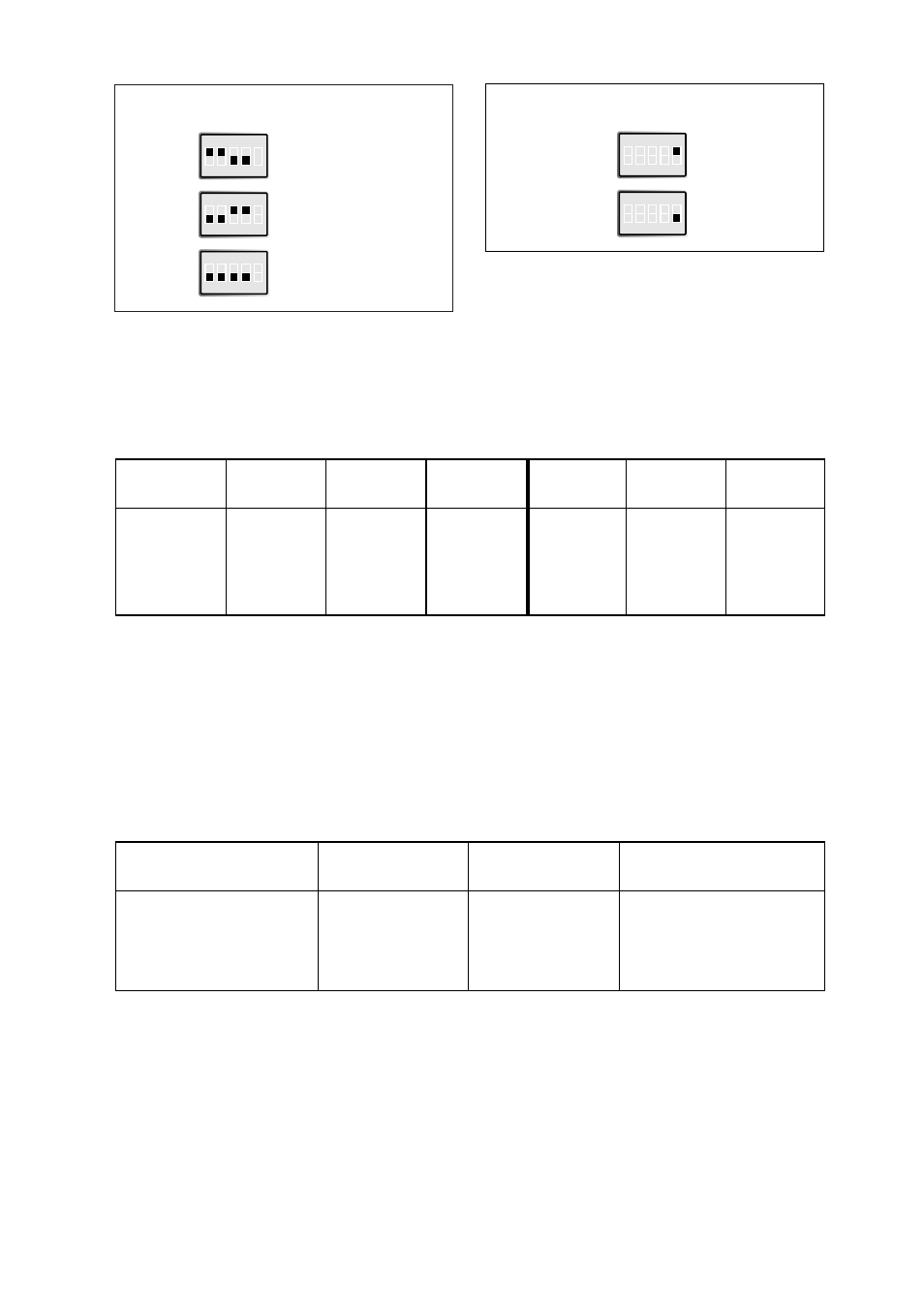
Termination with fail-safe 1)
S2
1) The fail-safe function forces the signal state of the
receiver to OFF when the connected transmitter is in
tri-state transmitter inactive). The receiver located
furthest away shall be terminated.
ON
1 2 3 4 5
Termination (2-wire)
S2
ON
1 2 3 4 5
Termination (4-wire)
S2
ON
1 2 3 4 5
No termination
Transmitted power
S2
ON
1 2 3 4 5
Low
S2
ON
1 2 3 4 5
High
Typical attenuation
in connectors
0.2-0.4 dB
Typical attenuation
in splice
Fusion 0.1
dB
Mechanical
0.2 dB
Power budget
Fibre
820 nm
1300 nm
Single mode
820 nm
1300 nm
Single mode
Min. values
Min. value
Min. value
Typ. value
Typ. value
Typ. value
50/125 µm
10.7 dB
62,5/125 µm
14.5 dB
11.6 dB
18.6 dB
15.1 dB
100/140 µm
20 dB
9/125 µm
6.3 dB
12.3 dB
Fibre
Attenuation Attenuation
Attenuation
at 820 nm
at 1300 nm
at single mode (1300 nm)
50/125 µm
3.0 dB/km
1.0 dB/km
62,5/125 µm
3.5 dB/km
1.2 dB/km
100/140 µm
4.0 dB/km
9/125 µm
0.5 dB/km
Attenuation in fibre cable
The values below can differ depending on quality and manufacturer of the fibre-optic
cable.
”Min. value” states the minimum guaranteed power budget. Experience shows however that the
typical value is in the range of the indicated ”Typ. value”.