Westermo MM-61 User Manual
Page 5
Attenuation in fibre cable
The values below can differ depending on quality and manufacturer of the fibre optic cable.
Fibre
Attenuation at 820 nm
50/125 µm
3,0 dB/km
62.5/125 µm
3,5 dB/km
200 PCS
4,0 dB/km
Typical attenuation in connectors
Typical attenuation in splice
0.2-0.4 dB
Fusion
0.1 dB
Mechanical 0.2 dB
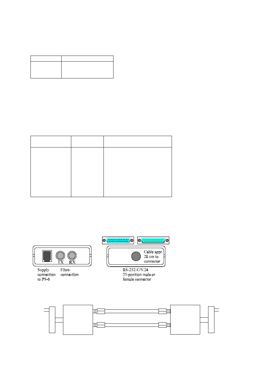
Connections MM-61
(25 pole D-sub female or 25 pole D-sub male)
Direction 1)
Connection no. Description
DCE DTE
I
O
2
TD1
O
I
3
RD1
I
O
4
TD2
O
I
5
RD2
-
7
SG/Signal Ground
O
I
8
RD3
I
O
20
TD3
O
I
9
RD4
I
O
10
TD4
1) I = Input O = Output on MM-61. TD= Transmitted Data and RD= Received Data.
The 4 channels can also be used for transmitting handshake signals like RTS,CTS,DTR
or signals for synchronous transmission Transmit Clock ( pin 15 )( DCE ), Receive Clock ( pin 17 )
and External Clock ( pin 24 )( DTE ).
Line connection
M M -6 1
T X
C h . 1
R X
C h . 1
M M -6 1
T X
R X