Westermo MRD-330 User Manual
Page 13
13
6623-2211
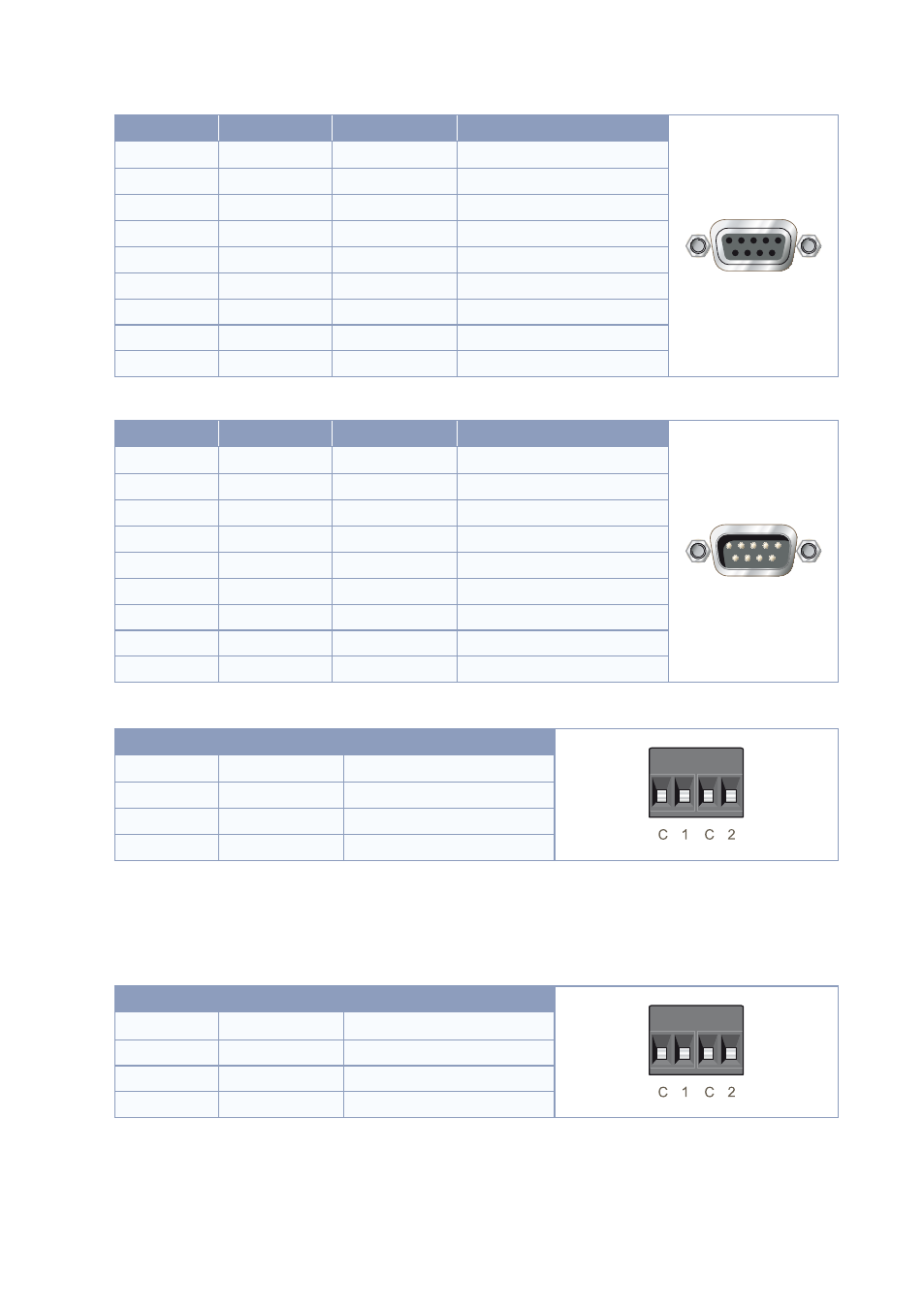
Modem Serial Port (DCE Female)
Position
Name
Direction
Description
5
1
9
6
1
DCD
Out
Data Carrier Detect
2
RxD
Out
Receive Data
3
TxD
In
Transmit Data
4
DTR
In
Data Terminal Ready
5
SG
–
Signal Ground
6
DSR
Out
Data Set Ready
7
RTS
IN
Request to Send
8
CTS
Out
Clear to Send
9
RI
Out
Ring Indicator
Modem Serial Port (DCE Male)
Position
Name
Direction
Description
1
5
6
9
1
DCD
In
Data Carrier Detect
2
RxD
In
Receive Data
3
TxD
Out
Transmit Data
4
DTR
Out
Data Terminal Ready
5
SG
–
Signal Ground
6
DSR
In
Data Set Ready
7
RTS
Out
Request to Send
8
CTS
In
Clear to Send
9
RI
In
Ring Indicator
Digital Input
Position
Direction
Description
1
In
Channel 1 – (Common)
2
In
Channel 1 +
3
In
Channel 2 – (Common)
4
In
Channel 2 +
The ground connection terminals on the digital input connector are at the same potential as the power supply
ground.
Westermo recommends that the unused plug connectors for the digital I/O-ports are connected to the unit at all
times.
Digital Output
Position
Direction
Description
1
Out
Channel 1 – (Common)
2
Out
Channel 1 +
3
Out
Channel 2 – (Common)
4
Out
Channel 2 +
The ground connection terminals on the digital output connector are at the same potential as the power supply
ground.
Westermo recommends that the unused plug connectors for the digital I/O-ports are connected to the unit at all
times.
Modem Serial Ports (DCE Female)
(for details, see next page)