1 i/o mapping, 2 update transmission times – Westermo RM-505U-2-E User Manual
Page 32
Advertising
505U Radio Telemetry Module
Page 32
© September 2002
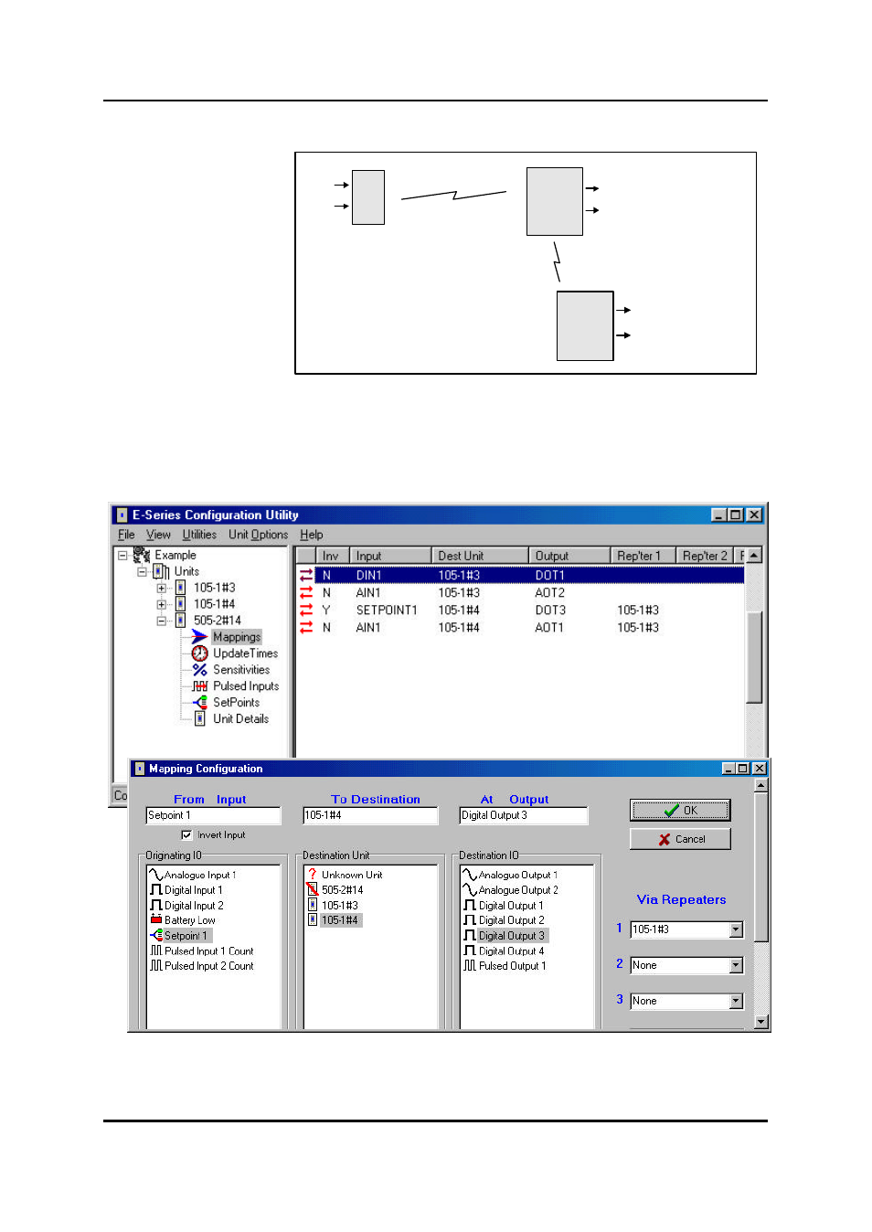
4.1 I/O Mapping
Enter I/O mappings as per
the 105U manual.
In the following example, a
digital input at a 505U is
mapped to DO1 of
105U#13. The analogue
inout of the 505U is
mapped to AO2 of the same module.
The setpoint status of the 505U is mapped (inverted) to DO3 of 105U#14, using 105U#13 as a
repeater. The 505U AI is also mapped to AO1 of this module. That is, the AI is mapped twice.
The mapping configuration for the 505U would be :
4.2 Update Transmission Times
505U
105U
105U
#14
#3
#4
DIN1
AIN
DO1 (DIN1 from #14)
AO2 (AIN from #14)
AO1 (AIN from #14)
DO3 (SP inv from #14)
Advertising