Westermo Viper-x12 User Manual
Page 14
Advertising
14
6641-2242
Viper-112-T3G / Viper-212-T3G
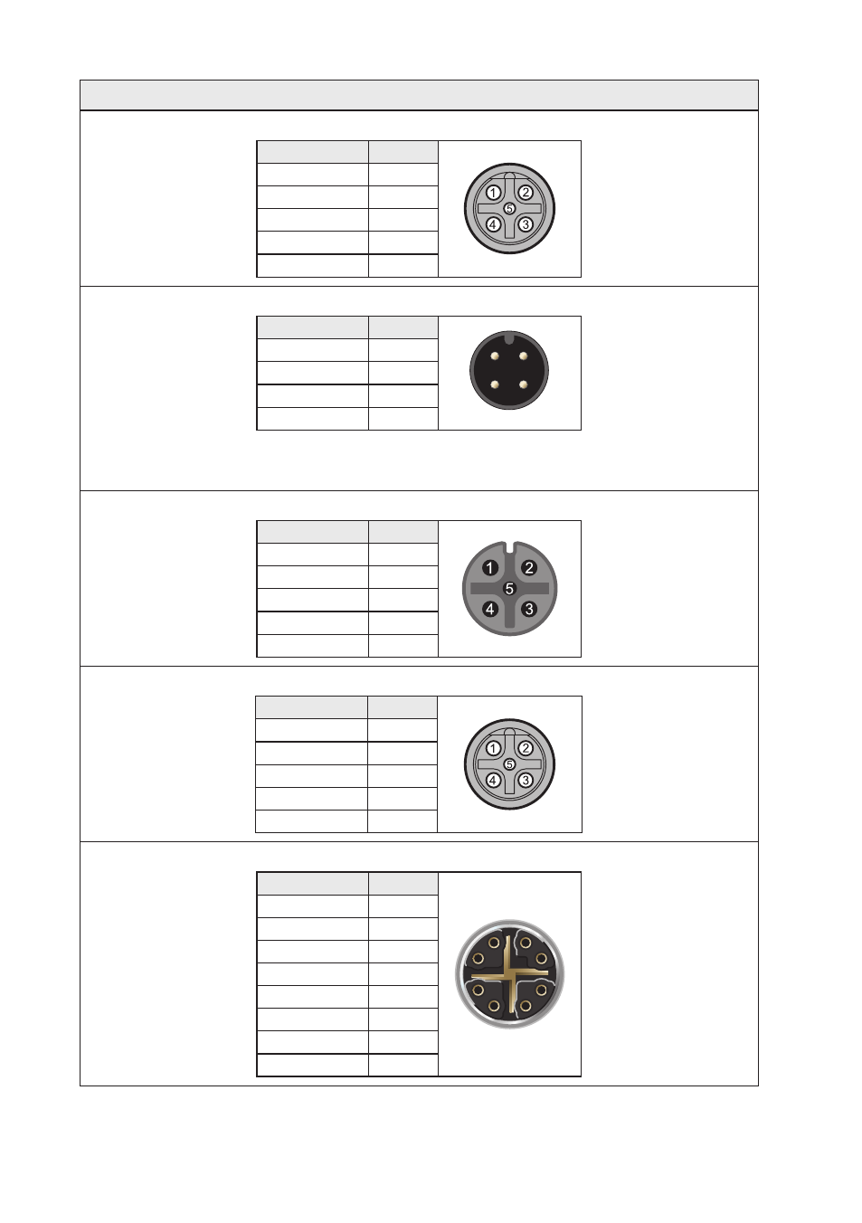
Ethernet connection
Pin number
Signal
No 1
TD+
No 2
RX+
No 3
TX–
No 4
RD–
Housing
Shield
Power connection
Pin number
Signal
2
1
3
4
No 1
+DC1
No 2
+DC2
No 3
-COM
No 4
-COM
Viper-x12-T3G supports redundant power connection.
The positive inputs are +DC1 and +DC2, the negative
input for both supplies are –COM.
USB
Pin number
Signal
No 1
DN
No 2
VBUS
No 3
NC
No 4
DP
No 5
GND
CON
Pin number
Signal
No 1
NC
No 2
TX
No 3
RX
No 4
NC
No 5
GND
GigE X4, X8, X12
Pin number
Signal
1
2
3
4
5
6
7
8
1
DA+
2
DA–
3
DB+
4
DB–
5
DD+
6
DD–
7
DC–
8
DC+
Advertising
See also other documents in the category Westermo Equipment:
- TR-36B (88 pages)
- TD-36 (44 pages)
- TR-36 (36 pages)
- TR-36B (20 pages)
- IDW-90 AT (97 pages)
- GD-01 (206 pages)
- GD-01 (20 pages)
- MRI-128-F4G (175 pages)
- MRI-128-F4G (169 pages)
- GDW-11 485 (380 pages)
- GDW-11 (40 pages)
- Lynx Series (28 pages)
- ODW-720-F2 (36 pages)
- ODW-720-F1 (20 pages)
- ODW-720-F1 (24 pages)
- ODW-730-F2 (36 pages)
- ODW-730-F1 (24 pages)
- DDW-120 (24 pages)
- DDW-226-EX (24 pages)
- DDW-226-EX (24 pages)
- DR-270 (28 pages)
- DR Series (460 pages)
- ED-2x0 (20 pages)
- MRD-3x0 (199 pages)
- FD-80 (24 pages)
- FDV-206-1D-1S (24 pages)
- GD-01 US (24 pages)
- LD-01 (8 pages)
- IDW-90 (44 pages)
- Lynx-x10-F2G (16 pages)
- Lynx-x08-F2G-S2 (20 pages)
- MDI-110-F3x (16 pages)
- MR-2x0 (28 pages)
- ODW-642 (28 pages)
- PII PoE Injector (12 pages)
- Viper Series (977 pages)
- SDI-5xx (12 pages)
- RFI-xx (32 pages)
- SDI-8xx (16 pages)
- RFIR-xxx (24 pages)
- TD-29 (16 pages)
- SDW-5xx (24 pages)
- TD-23 (24 pages)
- TD-29P (16 pages)
- Viper 408 (20 pages)