Westermo Viper-x12-p8 User Manual
Page 13
Advertising
13
6641-2252
Viper-112-P8 / Viper-212-P8
Viper-112-T3G-P8 / Viper-212-T3G-P8
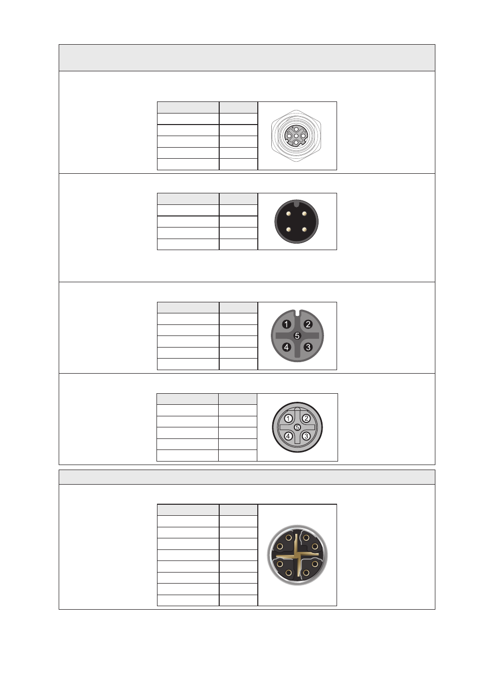
Ethernet connection
(X1-X12 on Viper-x12-P8, X1-X3, X5-X7, X9-X11 on Viper-x12-T3G-P8)
Pin number
Signal
No 1
TD+
No 2
RX+
No 3
TX–
No 4
RD–
Housing
Shield
Power connection
Pin number
Signal
2
1
3
4
No 1
+DC1
No 2
+DC2
No 3
-COM
No 4
-COM
Viper-12-PoE supports redundant power connection.
The positive inputs are +DC1 and +DC2, the negative
input for both supplies are –COM.
USB
Pin number
Signal
No 1
DN
No 2
VBUS
No 3
NC
No 4
DP
No 5
GND
CON
Pin number
Signal
No 1
NC
No 2
TX
No 3
RX
No 4
NC
No 5
GND
Viper-112-T3G-P8 / Viper-212-T3G-P8
X4, X8, X12
Pin number
Signal
1
2
3
4
5
6
7
8
1
DA+
2
DA–
3
DB+
4
DB–
5
DD+
6
DD–
7
DC–
8
DC+
Advertising