Installation, Marking & cutting, Bonding the tank – Airmar 1 kW—M260 User Manual
Page 3
Installation
Marking & Cutting
CAUTION: For optimal performance, the transducer must be
installed so the beam will be aimed straight down. This is accom-
plished by cutting the tank to match the deadrise angle of the hull.
CAUTION: Do not mark or cut the tank in the space labeled
“Do not cut above this line.”
1. The tank can be disassembled for installation in tight places.
Do not disassemble the tank unless it is necessary. If the tank
will be installed as one unit, lightly tighten the socket-head cap
screws that hold the two sections of the tank together with a
force not exceeding 50 in.-lb. (see Figure 1). Use the Allen
wrench supplied. Do not over tighten. (To remove the Allen
wrench from the handle of the transducer, use a blade
screwdriver. After use, replace the Allen wrench in the recess.)
2. When you are satisfied that the selected mounting location is
optimal, place the tank up-side-down on the hull (see Figure 5).
NOTE: The tank can be placed with either a short side or a long
side parallel to the centerline of the boat.
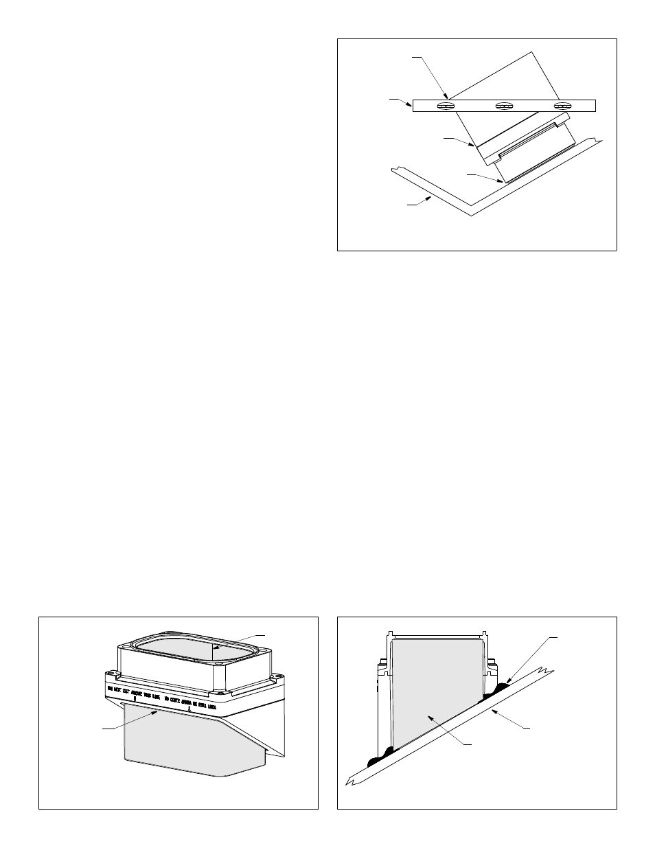
3. Holding a carpenter’s level even with the lower corner of one of
the sides to be cut, draw a level line on the tank. Repeat this
process on the opposite side of the tank. Connect the two lines
to form the SHORTEST side of the tank. Be sure the lines are
level, as they will be the cutting guidelines.
4. Before cutting the tank, be sure the TALLEST side will be
closest to the centerline (keel) of the boat after the tank is
installed. And be sure to observe the “Do not cut above this
line.” Using a saw, cut the three sides of the tank along the
guidelines drawn. It may be necessary to further shape the tank
to the hull to ensure a liquid-tight bond.
5. The tank is provided with a cork liner to reduce sound echoes.
After the tank has been cut, wrap the cork liner around the
inside of the tank (see Figure 6). Butt the sides of the liner along
the center of the tallest side. Push the cork liner up against the
top edge on the inside of the tank. Trace the bottom edge of the
tank onto the liner.
NOTE: There may be a gap between the butted edges which
will not affect performance.
6. Remove the cork liner from the tank. Use scissors to cut the
liner along the line drawn.
Bonding the Tank
CAUTION: The tank must be liquid-tight. To ensure a tight bond,
the hull surface under and around the tank must be smooth, free
of paint or any other finish, clean, and dry.
1. To ensure a tight bond, remove any paint or other hull finish. If the
surface is rough, use a disk sander to smooth an area slightly larger
than the tank. Clean any dust, grease, or oil from the hull surface
with a weak solvent, such as alcohol. Dry the effected area.
2. Use 80 grit sand paper to sand the outside and inside of the
tank up 50mm (2") above the bottom edge. Remove the dust
with a weak solvent, such as alcohol. Dry the effected area.
3. Use an approved bonding material (see “Tools & Materials” on
page 1). Glass the tank to the hull with fiberglass resin, using
standard fiberglass technique. Alternatively, apply a generous
bead of marine putty/sealant to the bottom edge of the tank
following the manufacturer’s instructions (see Figure 7). Press
the tank firmly in place. Apply a second bead around the inside of
the tank. And apply a third bead around the outside of the tank.
4. Allow the bonding material to cure. The seal must be liquid-tight.
5. If the tank is being installed in two parts, reattach the two
sections now (see Figure 1). Be sure the O-ring gasket is in place
around the lip and lubricated. Screw the two sections together
using the socket-head cap screws, lock washers, and flat
washers supplied. Use the Allen wrench to tighten the screws
with a force not exceeding 50 in.-lb. Do not over tighten.
3
Figure 5. Marking the cutting guidelines
(30° deadrise angle shown)
top
hull
carpenter’s
level
Draw a level line
Do not mark
below this line.
Copyright © 2006 - 2011 Airmar Technology Corp.
starting at the
Figure 6. Fitting the cork liner
(30° angle shown)
Copyright © 2006 - 2011 Airmar Technology Corp.
Figure 7. Bonding the tank
Copyright © 2006 - 2011 Airmar Technology Corp.
lower corner.
of tank
trace bottom
edge of tank
onto cork liner
possible
gap
fiberglass
hull
in place
or apply
three beads
of marine
after bonding
putty/sealant
material cures,
insert cork liner