7 electrical connections - general diagram, 8 connection to the gps antenna, Electrical connections - general diagram – ARAG Skipper LT - Satellite Navigator User Manual
Page 10: Connection to the gps antenna
Advertising
10
4.7
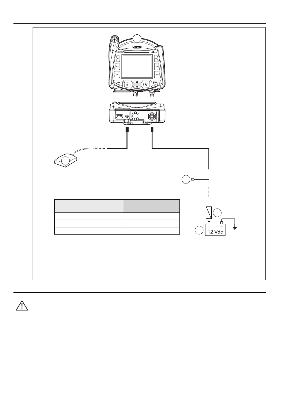
Electrical connections - general diagram
+
3 A
D
C
E
6 m
B
A
WIRE COLOR
(POWER CABLE)
RESPECTIVE
CONNECTION
black
negative
red
positive
green
treatment status signal
Fig. 10
a Satellite navigator
B GPS Antenna
c Battery
d Automotive fuse - 3 A
e Treatment status signal +12 Vdc (from main control valve)
4.8
Connection to the GPS antenna
Only use the specific ARAG GPS antenna to be used in connection with SKIPPER LT.
ARAG shall not be held liable for loss or damage due to use of different types of
antenna.
Before making the connection, carefully read par. 4.3 - General precautions for loca-
ting the SKIPPER LT and cable runs.
Connect the external GPS antenna to Skipper LT.
The connection points are given in par. 4.7 - Electrical connections - general diagram.
Advertising