Installation, 1 power and ethernet cable connection – ARM Electronics MP13DVPDN User Manual
Page 10
9
5. Installation
Please read the instructions provided in this chapter thoroughly before installing
the vandal proof IP Dome Camera.
5.1
Power and Ethernet Cable Connection
Power Connection
Make sure the camera’s power cable is correctly and firmly connected; refer to
the pin definition table in section 3.2 Camera’s Connectors. If using Power over
Ethernet (PoE), make sure Power Sourcing Equipment (PSE) is in use in the
network.
Ethernet Cable Connection
Use of Category 5 Ethernet cable is recommended for network connection; to
have best transmission quality, cable length shall not exceed 100 meters.
Connect one end of the Ethernet cable to the RJ-45 connector of the IP Dome
Camera, and the other end of the cable to the network switch or PC.
NOTE:
In some cases, you may need use an Ethernet crossover cable
when connecting the IP Dome Camera directly to the PC.
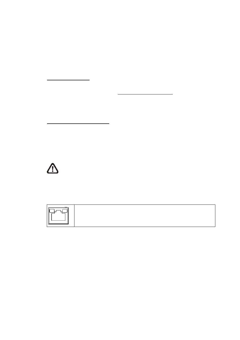
Check the status of the link indicator and activity indicator LEDs; if the LEDs are
unlit, please check LAN connection.
Green Link Light indicates good network connection.
Orange Activity Light flashes for network activity indication.