Configuration procedure, Figure 22, N in – H3C Technologies H3C S12500 Series Switches User Manual
Page 59: Figure 21, Figure 21 network diagram before irf configuration, Figure 22 network diagram for irf configuration
Advertising
51
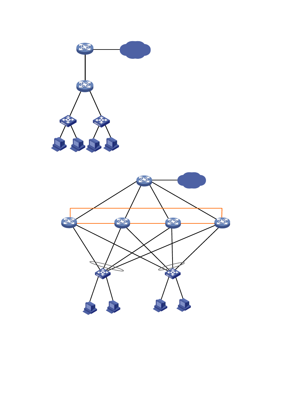
Figure 21 Network diagram before IRF configuration
Figure 22 Network diagram for IRF configuration
Configuration procedure
1.
Configure Device A:
# Set the member ID to 1 and the priority to 12.
<Sysname> system-view
Device A
Device E
IP network
XGE1/3/0/1
(IRF-port1/2)
XGE2/3/0/1
(IRF-port2/1)
XGE2/3/0/2
(IRF-port2/2)
XGE3/3/0/2
(IRF-port3/1)
XGE3/3/0/1
(IRF-port3/2)
XGE4/3/0/1
(IRF-port4/1)
XGE4/3/0/2
(IRF-port4/2)
XGE1/3/0/2
(IRF-port1/1)
Device A
Device B
Device C
Device D
Device E
IP network
The orange lines represent IRF links. The black lines represent Ethernet links. The gray circles represent aggregate links.
Advertising
This manual is related to the following products: