H3C Technologies H3C S7500E Series Switches User Manual
Page 285
21-2
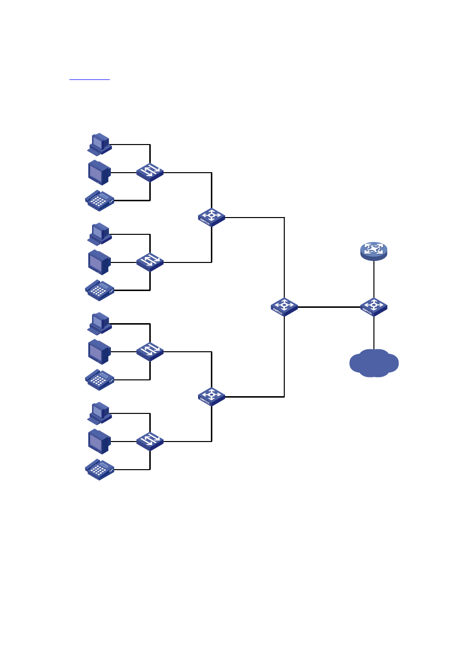
Application Scenario of One-to-One and Many-to-One VLAN Mapping
shows a typical application scenario in which each home gateway uses different VLANs to
transmit the PC, VoD, and VoIP services.
Figure 21-1
Application scenario of one-to-one and many-to-one VLAN mapping
VLAN 101 - 102 - > VLAN 501
VLAN 201 - 202 - > VLAN 502
VLAN 301 - 302 - > VLAN 503
...
Campus switch
Distribution
network
DHCP client
DHCP server
...
Wiring - closet
switch
VLAN 1 - > VLAN 101
VLAN 2 - > VLAN 201
VLAN 3 - > VLAN 301
VLAN 1 - > VLAN 102
VLAN 2 - > VLAN 202
VLAN 3 - > VLAN 302
PC
VoD
VoIP
VLAN 2
Home gateway
VLAN 1
VLAN 3
PC
VoD
VoIP
VLAN 2
Home gateway
VLAN 1
VLAN 3
Wiring-closet
switch
VLAN 1 - > VLAN 199
VLAN 2 - > VLAN 299
VLAN 3 - > VLAN 399
VLAN 1 -> VLAN 200
VLAN 2 -> VLAN 300
VLAN 3 -> VLAN 400
PC
VoD
VoIP
VLAN 2
Home gateway
VLAN 1
VLAN 3
PC
VoD
VoIP
VLAN 2
Home gateway
VLAN 1
VLAN 3
...
VLAN 199 - 200 - > VLAN 501
VLAN 299 - 300 - > VLAN 502
VLAN 399 - 400 - > VLAN 503
...
...
...
...
To further sub-classify each type of traffic by customer, perform one-to-one VLAN mapping on the
wiring-closet switches, assigning a separate VLAN for each type of traffic from each customer. The
required total number of VLANs in the network can be very large. To prevent the maximum number of
VLANs from being exceeded on the distribution layer device, perform many-to-one VLAN mapping on
the campus switch to assign the same type of traffic from different customers to the same VLAN.
Because the campus switch preserves the original VLAN information, the traffic flows from different
customers are segregated, even though they appear to be in the same VLAN.