S3100v2-8tp-pwr-ei, Front panel, Rear panel – H3C Technologies H3C S3100V2 Series Switches User Manual
Page 12: Right side panel
Advertising
6
S3100V2-8TP-PWR-EI
Front panel
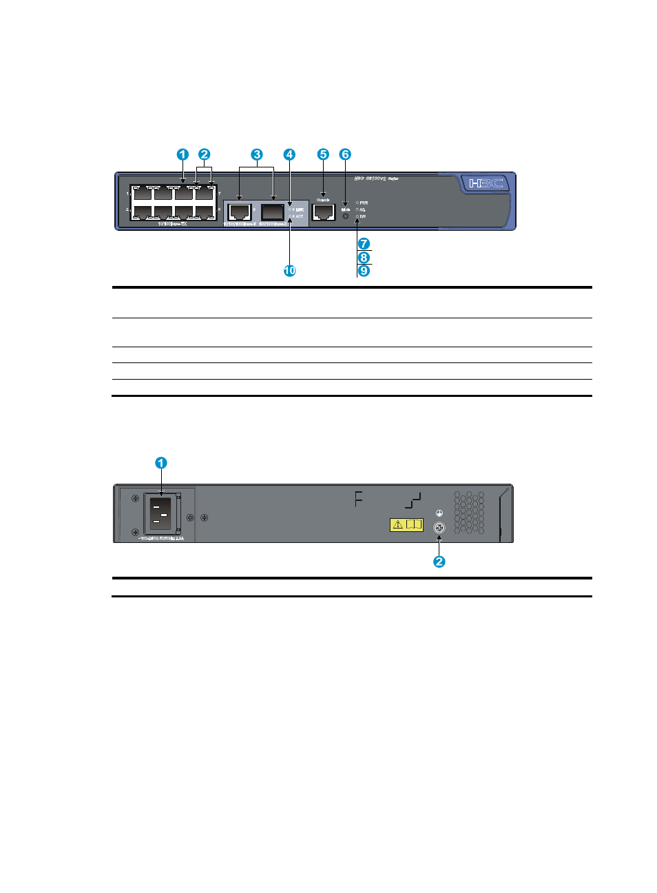
Figure 11 S3100V2-8TP-PWR-EI front panel
(1) 10/100Base-TX Ethernet port
(2) 10/100Base-TX Ethernet port LEDs (left: yellow,
right: green)
(3) Combo interface (10/100/1000Base-T Ethernet
port on the left, 100/1000Base-X SFP port on the right)
(4) LINK LED for a combo interface
(5) Console port
(6) Port LED mode switching (Mode) button
(7) Power (PWR) LED
(8) Port mode (A/L) LED
(9) Port mode (D/S) LED
(10) ACT LED for a combo interface
Rear panel
Figure 12 S3100V2-8TP-PWR-EI rear panel
(1) AC-input power receptacle
(2) Grounding screw
Right side panel
The S3100V2-8TP-PWR-EI switch has one security lock slot on the right-side panel to prevent theft. You
must purchase a cable lock separately.
Advertising