Msr 20-13 router, Appearance – H3C Technologies H3C MSR 20-1X User Manual
Page 15
Advertising
8
MSR 20-13 Router
Appearance
1.
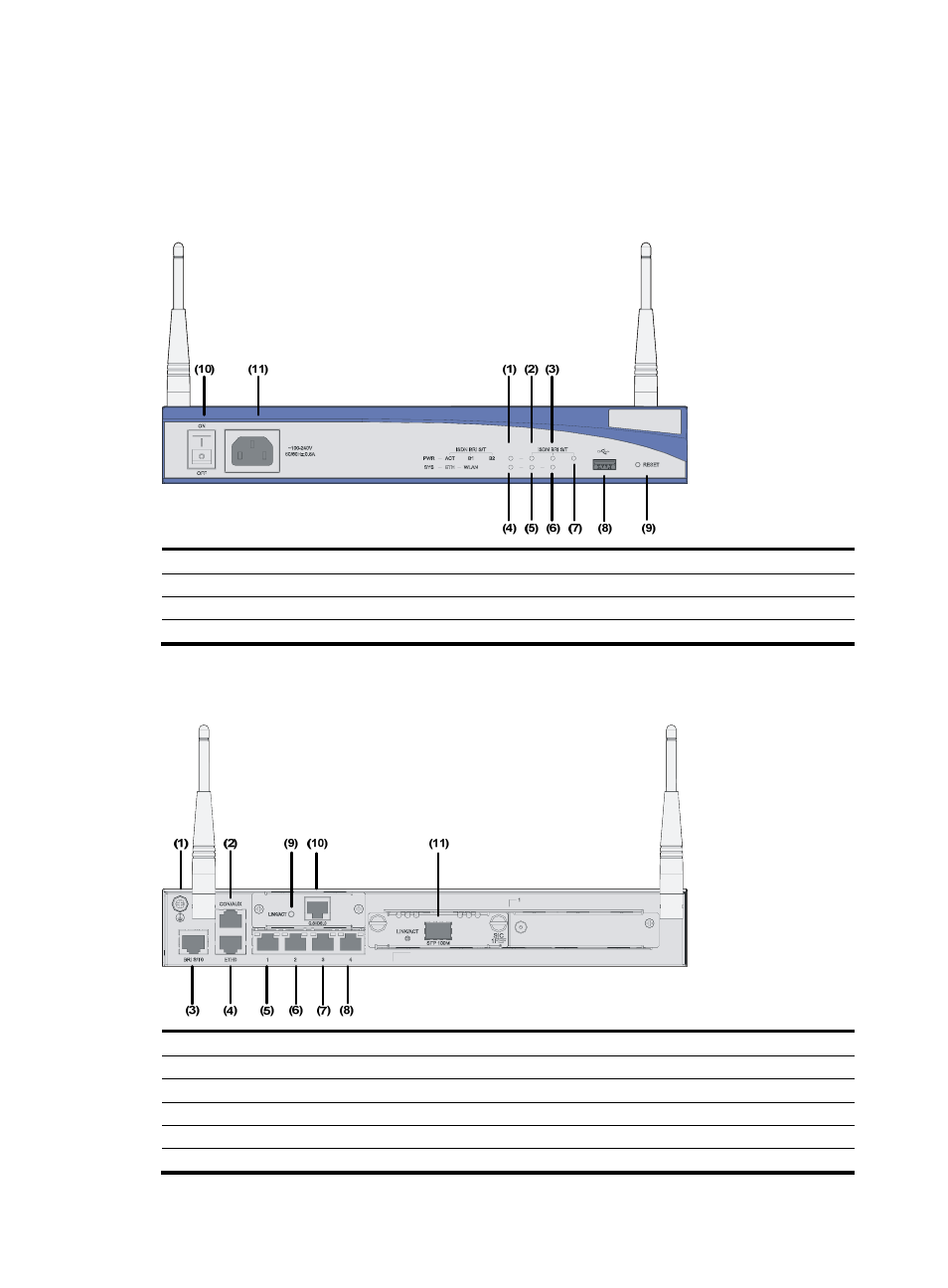
Front panel
Figure 7 Front panel of the MSR 20-13 router
(1) Power LED (PWR)
(2) ACT LED of BRI interface
(3) B1 LED
(4) System LED (SYS)
(5) Ethernet LED (ETH)
(6) Wireless LED (WLAN)
(7) B2 LED
(8) USB interface
(9) RESET button
(10) Power switch
(11) Power socket
2.
Rear panel
Figure 8 Rear panel of the MSR 20-13 router
(1) Grounding terminal
(2) Console port/Auxiliary port (CON/AUX)
(3) BRI S/T interface
(4) Layer 3 Ethernet interface 0 (ETH0)
(5) Layer 2 Ethernet interface 1
(6) Layer 2 Ethernet interface 2
(7) Layer 2 Ethernet interface 3
(8) Layer 2 Ethernet interface 4
(9) G.SHDSL.BIS LED
(10) G.SHDSL.BIS interface
(11) SIC/DSIC slot
Advertising
This manual is related to the following products: