Tracking input/output, Reference loop-through input, Connecting balanced audio connections. see – Grass Valley 8921ADT User Manual
Page 13
8921ADT Instruction Manual
13
Installation
To use J11 and J12 as unbalanced audio outputs if a tracking input or output
is not required, jumper J5 to pins 1-2 (AES1) and J6 to pins 1-2 (AES2). Refer
to
.
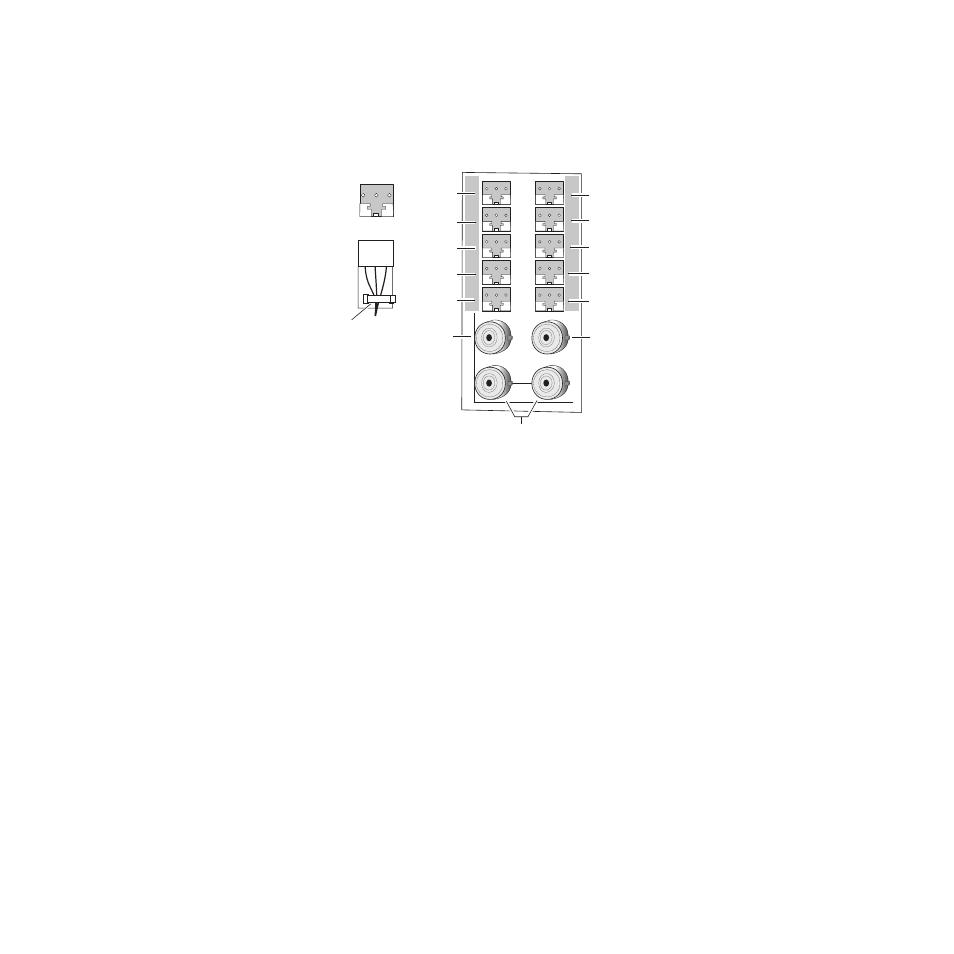
Figure 4. 8921ADT Rear Input/Output Connectors
Tracking Input/Output
A Tracking Input is provided at BNC J11. Connect an RS-232 level auto
tracking signal from a video frame synchronizer (such as an 8900FSS or
8981FS) to this BNC and set jumper J5 (
) to TRK IN
(pins 2-3).
If you need to loop the tracking input signal to another destination, a buff-
ered looping output is available at BNC J12. To make this Tracking Output
available, jumper J6 (
) to pins 2-3 (TRK OUT).
If no input and/or output audio tracking is needed, these BNCs can be
jumpered to provide additional unbalanced AES 1 and AES 2 BNC outputs
as described in
Reference Loop-through Input
Connect an NTSC/PAL analog color black reference, AES 48 kHz Word
Clock signal, or 48 KHz AES3-id DARS signal to one of the loop-through
reference connectors, J13 or J14. Terminate the unused connector into 75
Ω
if the signal is not looped to other equipment.
J2
J1
J3
J5
J7
J9
J2
J4
J6
J8
J10
J11
J13
J12
J14
IN
8204_03
AES 1-1
AES 1-2
AES 1-3
AES 2-1 (Set jumper J2 for BAL or UN outputs
on both AES 1-1 and AES 2-1)
AES 2-2 (Set jumper J3 for BAL or UN output
on both AES 1-2 and AES 2-2)
AES 2-3 (Set jumper J4 for BAL or UN output
on both AES 1-3 and AES 2-3)
Looping
Reference Input
Tracking Input
(J5 set to 2-3)
or
AES 1 Out
(J5 set to 1-2)
Tracking Output
(J6 set to 2-3)
or
AES 2 Out
(J6 set to 1-2)
Audio In 1
Audio In 3
Audio In 2
Audio In 4
+ - G
Strain relief
Secure with
cable tie
+ - G