Grass Valley 8943FC User Manual
Page 16
16
8943FC — Instruction Manual
Installation
3.
The finished installation should look like the example in
. The
label will list the GV Model number, the GV part number, and the
manufacturer’s part number. Also note the two arrows on the label will
indicate signal direction as shown in the dual receiver example in
(arrows pointing in). A dual transmitter will have two arrows
pointing out, and a transceiver will have one input and one output
arrow.
Figure 6. Finished Bracket Mounting
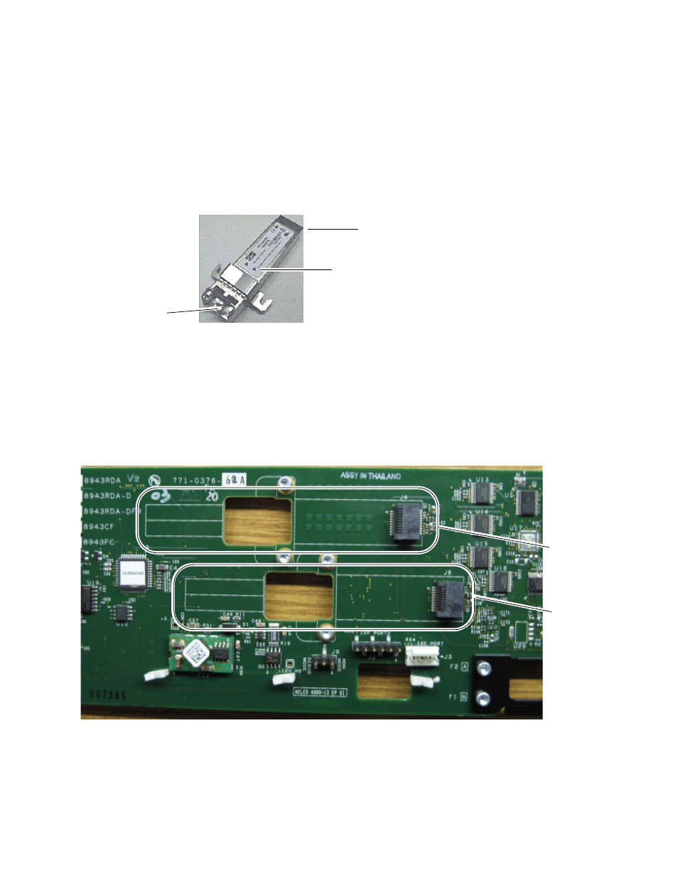
Once you have put the mounting brackets onto the two SFP devices, install
them on the top side of the circuit board and cable them to the output con-
nectors on the main module with the fiber cable assembly provided.
shows an example of a finished SFP installation on a 8943FC
module with the locations of the hardware components, connectors, and
plastic cable guides.
Figure 7. Example of a Finished SFP Installation
Fiber cable connectors
SCA-2 (electrical) connector
Arrows indicating SFP device type
J4 - F3/F4
J6 - F1/F2