Functional description, Serial 4:2:2 input stage & output – Grass Valley 8960ENC v.8.1.0 User Manual
Page 45
8960ENC—Instruction Manual
45
Functional Description
Functional Description
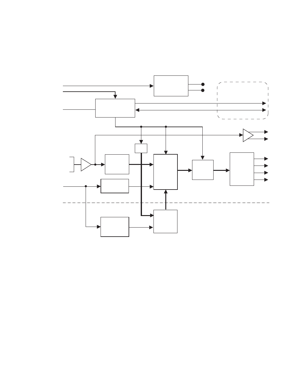
Refer to the block diagram in
while reading the following func-
tional description.
Figure 24. 8960ENC Block Diagram
Serial 4:2:2 Input Stage & Output
The SDI signal is connected to the high impedance loop-through input. The
input amplifier auto-equalizes the signal up to 24 dB loss (300 meters of
Belden 8281 cable). The reclocked signal is available on two SDI output con-
nectors and also on an internal 10-bit parallel bus for further processing.
Error Detection Handling (EDH) is tested by the microcontroller which
flashes the Fault LED when errors are detected.
+12V
Module Slot ID
Fault Reporting
Local User
Interface
Intra-frame Control Interface
4:2:2
SDI
Input
10
10
10
4X NTSC/PAL
2X SDI
Optional Submodule *
Available with Frame
Communication Upgrade
* The main encoder module automatically recognizes the attachment of the frame synchronizer submodule.
NTSC/PAL
Reference
-5V
+5V
Microcontroller
On-board
Switching Mode
Power Supply
module
Serial to
Parallel
Converter
EDH
Frame Delay/
Synchronizer
H Genlock to
External Video
Color Frame
ID Generation
Output
Filter and
Driver
Cross-color
Remover
&
Genlock
with
FIFO
10-bit
Composite
Encoder
0642-01
RC