Power up, Operation indicator leds – Grass Valley 8964MON User Manual
Page 11
8964MON Instruction Manual
11
Power Up
Power Up
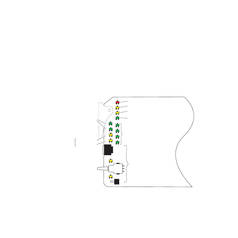
The front LED indicators and configuration switches are illustrated in
. Upon power-up, the green PWR LED should light and the yellow
CONF LED should illuminate for a few seconds for the duration of module
initialization.
Operation Indicator LEDs
With factory default configuration and a valid input signal connected, the
green PWR LED and one of the green signal standard LEDs (525 or 625)
should illuminate (refer to
to see the possible operating
indicator combinations).
Video input presence on each encoder channel is indicated by the
CH1–CH4 green LEDs on.
Figure 4. LEDs and Configuration Switches
FUNCTION
FA
U
LT
525
625
CM1
CM0
2ND
UP
DOWN
CSM
CH1
CH2
CH3
CH4
COMM
CONF
PWR
8367_06
2ND LED
PWR – Green LED on indicates power OK.
FAULT – Red LED is off during normal operation.
COMM – Yellow LED on indicates frame bus traffic.
CONF – Yellow LED on indicates module is initiating,
changing operating mode, or programming hardware.
Module Configuration Switches and LEDs.
CH 1 – CH4 Green LEDs on indicates
signal present on CH1, 2, 3 and 4.
Not Used
Module Configuration
Active Channel
Control Indictors
CM1 – Yellow LED
CM0 – Yellow LED
MODE
CNTRL