Power up, Operation indicator leds – Grass Valley 8981FS User Manual
Page 13
8981FS Instruction Manual
7
Power Up
Power Up
The various front LED indicators and configuration switches are illustrated
in
. Upon power-up, the green PWR LED should light and the
yellow CONF LED should illuminate for the duration of module initializa-
tion.
Operation Indicator LEDs
With a valid input signal connected, the green PWR LED and one of the
green signal standard LEDs (525 or 625) should illuminate.
Video input presence is indicated by the 525 or 625 LED (indicating a 525-
line or 625-line input signal has been detected).
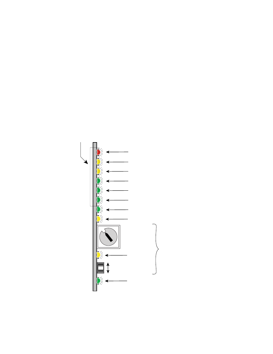
Figure 4. LEDs and Configuration Switches
A red FAULT LED indicates an error situation. When in Frame Sync mode,
the 525 or 625 LEDs will blink if the reference signal input line standard
does not match the video input standard.
16-position
Rotary switch
Momentary toggle switch
525 – Green LED on indicates 525-line input present
PWR – Green LED on indicates power OK
FAULT – Red LED is off during normal operation
Ejector Tab
COMM – Yellow LED on indicates communication bus traffic
CONF – Yellow LED on indicates module is initiating, changing operating
mode, or updating firmware
REF – Green LED on indicates Reference signal present
FRZ – Yellow LED on indicates output is in Freeze mode
625 – Green LED on indicates 625-line input present
Module Configuration Switches and LED
2ND FUNC LED
(yellow)
DELAY – Green LED on indicates module is operating in fixed delay mode
0719_06
0
1
2
3 4
5 6 7
8
9
A
B
CD
E
F