Cameraman 3-ccd digital camera, Figure 4. front of camera, Lens shroud – Grass Valley 3-CCD CameraMan User Manual
Page 10: Figure 5. lens shroud, Camera control block
Advertising
10
CameraMan Installation and Operation Manual
Section 1 — General
CameraMan 3-CCD DIGITAL Camera
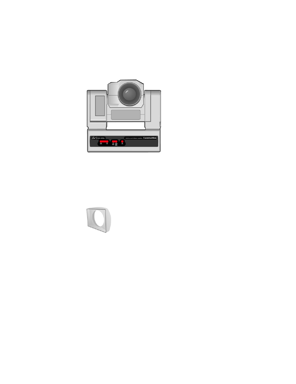
The camera and its integrated intelligent pan/tilt system is the primary
component, and the basis for all of Grass Valley’s CameraMan camera sys-
tems.
Figure 4. Front of Camera
Lens Shroud
The 20x version of the 3-CCD DIGITAL Camera includes a rectangular lens
shroud (
Figure 5. Lens Shroud
Camera Control Block
The camera control block should be attached to the back of the camera. This
box is the point of connection for all RS-232 and RS-485. The only time this
box needs to be removed is if the camera is upgraded to a Presenter Camera
System.
Note
If a Presenter or Deluxe Camera System was purchased, the camera control
block is not needed.
Advertising