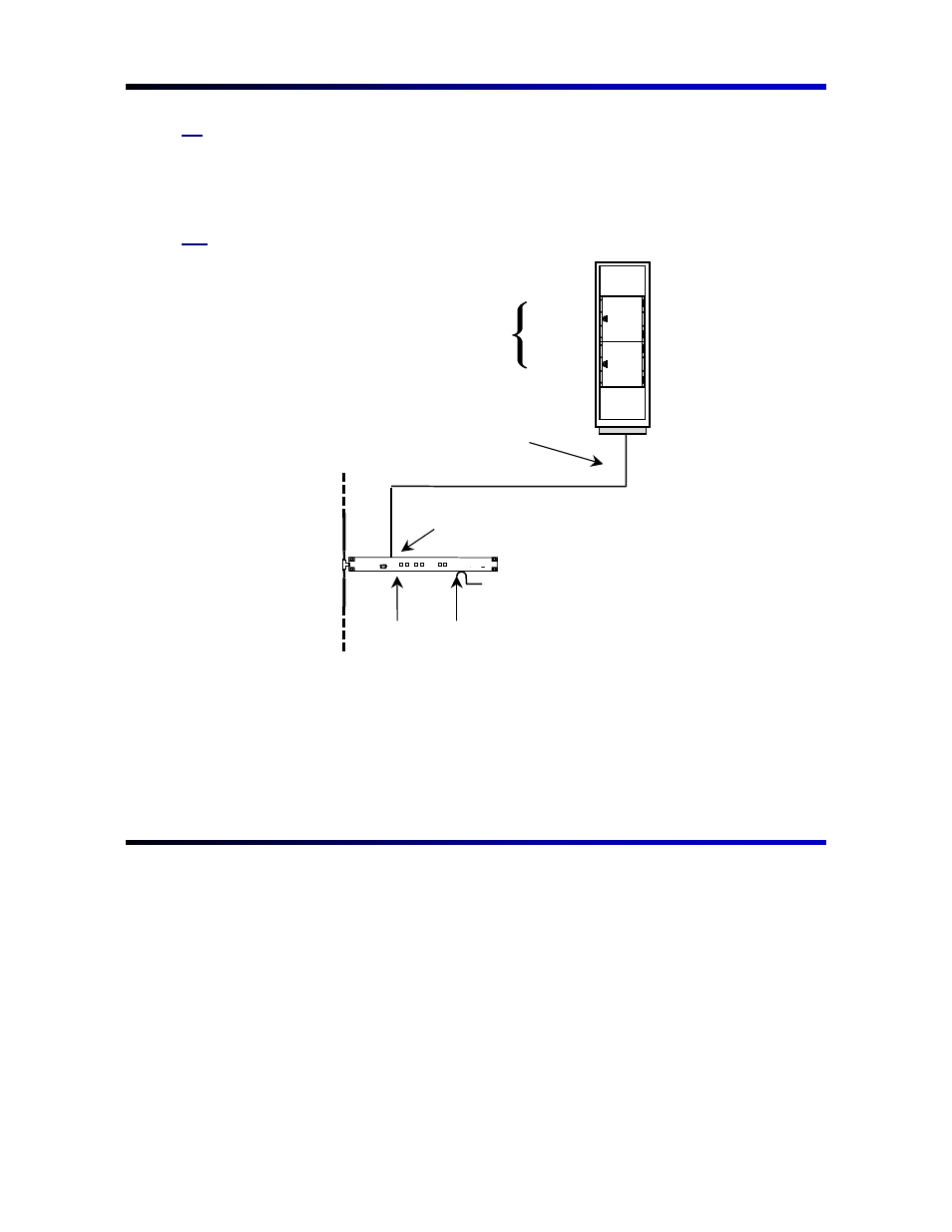
Figure 2. control panel installation – Grass Valley Jupiter Control System User Manual
Page 5
Advertising
3
G
G
e
e
t
t
t
t
i
i
n
n
g
g
S
S
t
t
a
a
r
r
t
t
e
e
d
d
w
w
i
i
t
t
h
h
H
H
a
a
r
r
d
d
w
w
a
a
r
r
e
e
To the customer:
Someone once said that a picture is worth a thousand words. Concerning the Jupiter
set up, this statement is certainly true. The diagrams below should make the
hardware set up quite simple.
Figure 1. Connection to Philips/Thomson routing switchers
VM 3000
Control
Processor
LAN
House sync required for
vertical interval switching.
House T/C
(Optional)
Binary protocol
Crosspoint bus port
15-pin CC 2010 Matrix (crosspoint bus) data cable
For jumper and
switch setting
information, refer
to the hardware
manual supplied
with the switcher.
SDR 400
Mars
Venus
Trinix
Advertising