Grass Valley Kalypso Emergency Bypass Option User Manual
Page 14
14
Kalypso Emergency Bypass Option Instruction Manual
Installation
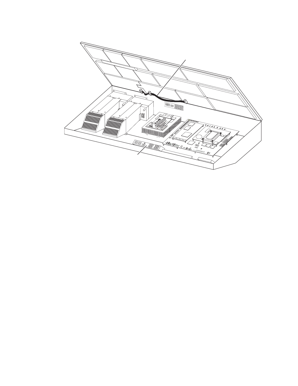
Figure 5. 2-M/E System Old Ribbon Cable
Local Aux Processor Interface Board Version
2.
Determine which type of Local Aux Processor board (
Figure 5
) is
installed in your system. Cable installation is different depending on
board type. The part number of the board is visible behind the fan
assembly.
•
If the part number is lower than 671-4945-02, the board will not
work with the Emergency Bypass option. Do not remove or replace
the cable. Contact Grass Valley Customer Service for an upgrade.
•
If 671-4945-02, go to
Older Board Cable Replacement (671-4945-02) on
page 14
.
•
If 671-4945-03, go to
Newer Board Cable Replacement (671-4945-03) on
page 15
.
Older Board Cable Replacement (671-4945-02)
1.
Power off the 2-M/E Main panel.
2.
Remove the old ribbon cable from the lid (
Figure 5
).
3.
Attach the two closely spaced connectors on the new cable to the same
two boards in the lid (
Figure 6
). The red marked edge of the ribbon
cable must face down toward the hinge of the lid, to match the pin 1 and
2 side of the connector. These connectors are keyed for this orientation.
0721_07_68_r0
Old Cable
To Be Replaced
SATELLIT
E PORT
S
TRANSM
IT
RECEIV
E
8 8 8
8 8 8
8 8
TRANSM
IT
GP8
GP7
GP6
GP5
GENERA
L
PURPOS
E
LEDS
GP4
GP5
GP1
GP0
RECEIV
E
SATEL
LITE P
ORTS
FAULT
INIT
RUN
XMT
C119
RCV
LINK
RTP/C
ONTR
OL PA
NEL L
AN
ACTIV
ITY
COLN
C29
3.3V
R151
R152
POW
ER SU
PPLIE
S
MENU
PROC
ESSO
R
RESE
T
R153
5V
12V
SCSI
HARD
DISK
5 6
7
8
9
0
1
2
34
Local Aux Processor
Interface Board