Grass Valley Kalypso Emergency Bypass Option User Manual
Page 15
Kalypso Emergency Bypass Option Instruction Manual
15
Installation
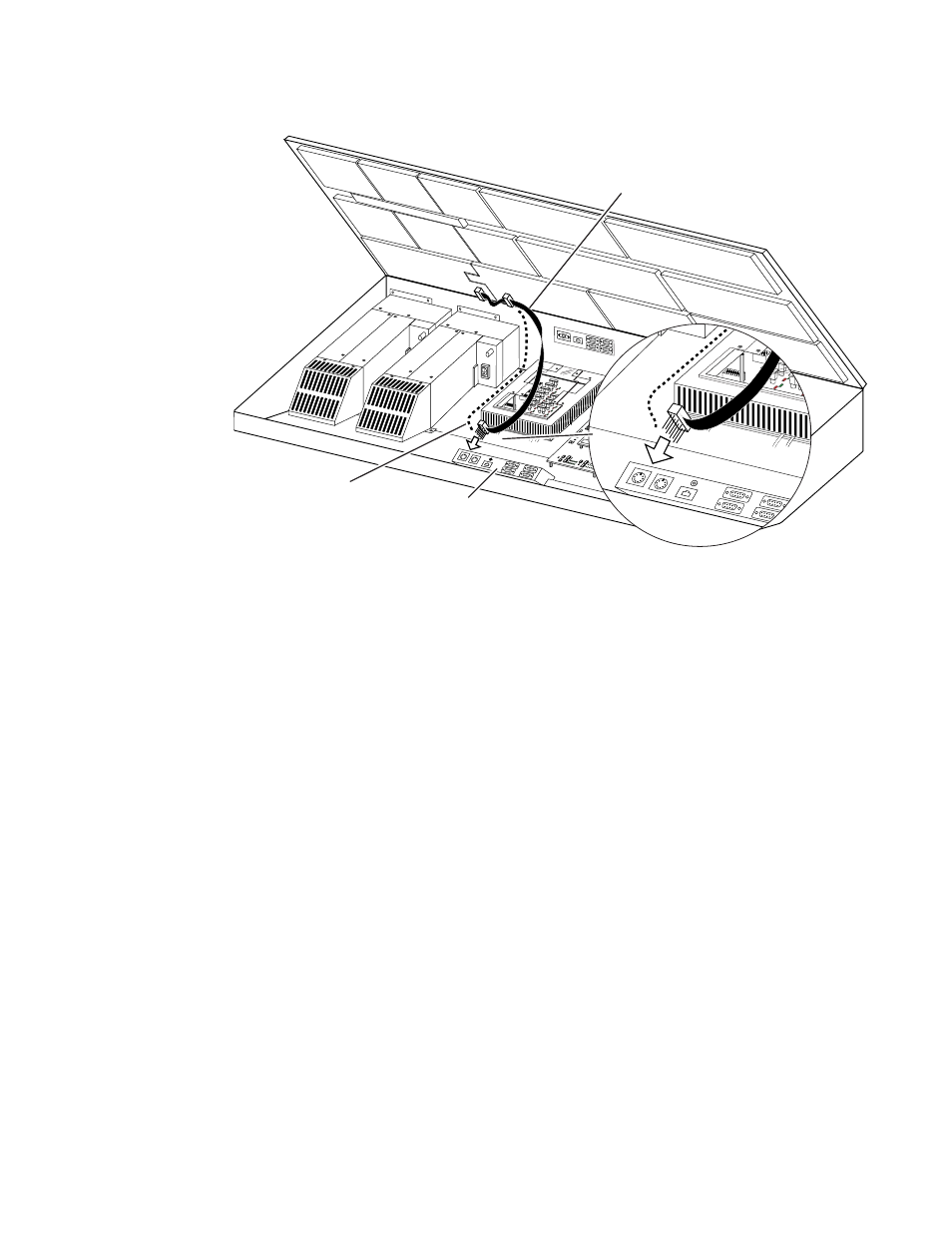
Figure 6. Older Board (671-4945-02) Cable Installation
4.
An interconnecting dual 10-pin header assembly with short and long
pins is provided with the kit. If not already installed, insert the side of
the assembly with the short pins into the remaining open ribbon cable
connector, making sure all connector sockets are filled.
CAUTION Use care when connecting the ribbon cable to the Local Aux Processor Inter-
face board. The connector is not keyed, and equipment damage can occur if
the connector is installed misaligned with the pins.
5.
The remaining connector with the header assembly pins protruding
attaches to the J3 connector on the lower left corner of the 671-4945-02
Local Aux Processor Interface board. Orient the cable with the ribbon
emerging from the right side of the connector. The red marked edge of
the ribbon cable must face down toward the bottom of the tub,
matching the pin 1 and 2 side of the connector on the board.
6.
Route the cable alongside the power supply (
Figure 6
), using the
supplied adhesive cable restraints.
7.
Close the lid and power up the Main panel.
Newer Board Cable Replacement (671-4945-03)
1.
Power off the 2-M/E Main panel.
2.
Remove the old ribbon cable from the lid (
Figure 5
).
0721_07_69_r2
New Replacement
Cable
Local Aux Processor
Interface Board
(Older Model )
SATELLIT
E PORTS
TRANSM
IT
RECEIV
E
8 8 8
8 8 8
8 8
TRANSM
IT
GP8
GP7
GP6
GP5
GENERA
L
PURPOS
E
LEDS
GP4
GP5
GP1
GP0
RECEIV
E
SATEL
LITE P
ORTS
FAULT
INIT
RUN
XMT
C119
RCV
LINK
RTP/C
ONTR
OL PA
NEL L
AN
ACTIV
ITY
COLN
C29
3.3V
R151
R152
POW
ER SU
PPLIE
S
MENU
PROC
ESSO
R
RESE
T
R153
5V
12V
SCSI
HARD
DISK
5 6
7
8
9
0
1
2
34
Final
Cable
Routing