Installation procedures – Grass Valley MPEG Upgrade User Manual
Page 15
Installation Procedures
MPEG Board Upgrade Installation
5
Installation Procedures
The procedures that follow take you step-by-step through the installation of
MPEG boards. You can install the board with the Profile chassis fully extended on
the rack slides if the instrument rack is adequately anchored to prevent tipping, and
if there is sufficient slack in the cables connected to the rear panel to allow the
chassis to fully extend on the slides. If you decide to keep the chassis in the rack
during the installation, it is a good idea to loosen any screws that need to be
removed from the back of the Profile unit before sliding it forward on the racks.
You will have to read the appropriate installation procedure first to determine
which screws must be loosened.
WARNING: Unless the instrument rack is adequately anchored, the rack
could tip when the chassis is extended on the rack slides. To avoid possible
injury, make sure the rack is secured firmly before extending the Profile
chassis on the rack slides.
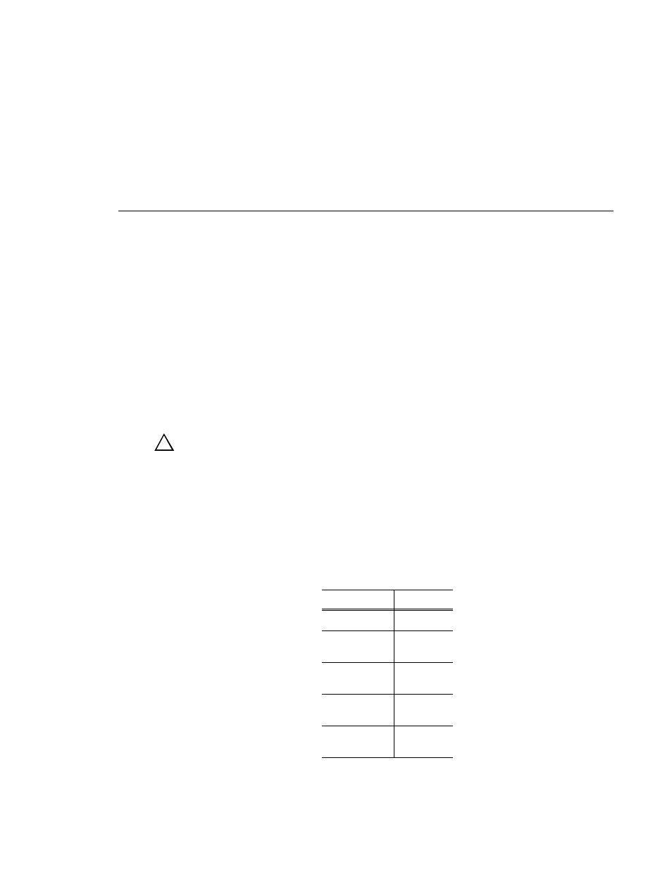
During the installation, you will be instructed to removed the three-slotted PCI
Interconnect board and replace it with the five-slotted board provided in this field
kit. The center slot on the five-slotted PCI board must be aligned with the Master
EDR board and the MPEG boards must be aligned with the outside slots of the PCI
board, that is, J8 and J12. See Table 3 for all PCI board locations.
!
Table 3. PCI board locations
Board
Slot
Master EDR
J10
Slave EDR
(if present)
J11
Fibre Channel
(if present)
J9
MPEG encoder
(preferred)
J8
MPEG decoder
(preferred)
J12