Area f - fiber connector, T-pov 324 camera unit rear panel detail – Grass Valley T-POV Bidirectional Robotic User Manual
Page 56
Advertising
50
T-POV 324 Components
T-POV 324 Camera Unit Rear Panel Detail
Area F - Fiber Connector
Fig. 4-23: T-POV 324 Camera Unit Front Panel -- Area f
Fiber Connector: SMPTE 304M Hybrid power fiber connection carries signals to and from
the Base Station and 95 Watts of12 Volt power from the base station.
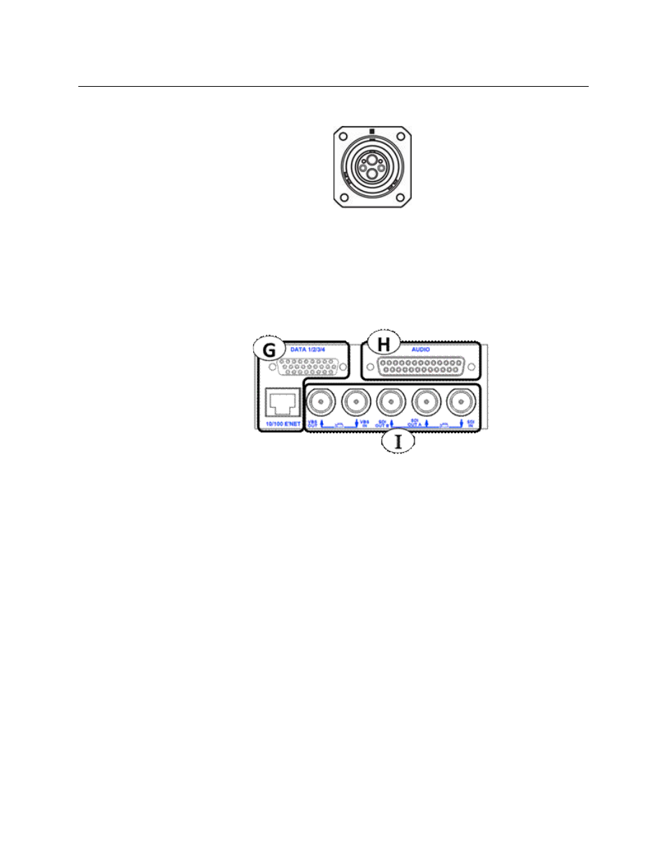
T-POV 324 Camera Unit Rear Panel Detail
The Camera Unit rear panel Area diagram is repeated for reference.
Fig. 4-24: T-POV 324 Camera Unit Rear Panel Detail
The T-POV 324 Camera Unit Rear Panel has three features:
• G: Data & Ethernet Connectors
• H: Audio Multi-Pin Connector
• I: Video Connectors
The rear connector panels of all versions of the T-POV 324 Camera Unit are identical in
physical configuration and in function.
Advertising