Telethon 3g rear panel features, Area f- rear panel power connectors – Grass Valley Telethon 3G User Manual
Page 17
13
Telethon 3G
User Guide
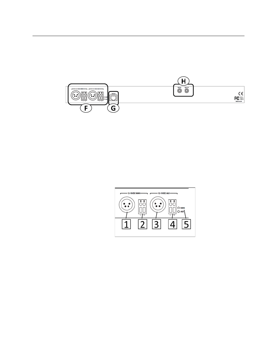
Telethon 3G Rear Panel Features
The Telethon 3G illustration is repeated for ease of use of this guide. All Telethon 3G units
operate the same: the only difference is in whether the Fiber Optic ST connectors are Inputs
or Outputs.
Fig. 3-7: Telethon 3G Rear Panel
Area F- Rear Panel Power Connectors
The Telethon 3G provides for the use of redundant 12-18 Volts DC power supplies. A battery
backup option is not provided for the Telethon 3G unit.
Power can be supplied to the unit by either a four-pin XLR connector from an external
power supply such as a ADAP-AC-04 or with direct wiring from a 12-18 Volt DC power
supply connected to the provided terminal block.
The main power supply can be of one type (XLR or direct wire) while the Aux power supply
is of the other type.
Fig. 3-8: Rear Panel Power Connectors
• 1 & 2 – Connectors for the Main 12-18 VDC power supply (XLR and Direct wire
terminal block)
• 3 & 4 – Connectors for the Main 12-18 VDC power supply (XLR and Direct wire
terminal block)
• 5 – MAIN/AUX Indicator LEDs – the LED for each power supply will be Green if power is
being applied to the Telethon 3G. If both Main and Aux are connected to a power
source, both LEDs will be Green. A lit LED is not an indication of which power source is
being used at the time: it only indicates that the power source is good.